


Part Number: TMS320F28335
Other Parts Discussed in Thread: C2000WARE
Tool/software:
Hey guys, I am new to this DSP F28335. I am trying to configure a double pulse code on CC studio with F28335 microcontroller but I am not sure what is going on. I have this sample code (see attached), when I connect this to my oscilloscope, what I notice was 2 pulses but it is not what I expected. There are two issues,
- Before debugging, the DC voltage was constant high, and after debugging, my t1 (which is suppose to be high) was instead low, and t2 (which is suppose to be low) was instead high, and t3 (which is suppose to be high) was instead low, and after t3 I wanted it to be low all the way (i.e end of my double pulse).
- Next, The desired double pulse timing I am trying to achieve was t1 (2.5us) , t2 (1.5us) , t3 (1.5us) where t1 and t3 is high, and t2 is low. But when I measure the time period on my oscilloscope, t1 was 15us, and t2,t3 was 7.5us which is different from my code I not sure why?
My goal is to: Once debug, it should be low before t1, and at t1 it should be high for 2.5us, and at t2 it should be low for 1.5us, and at t3 high again for 1.5us, then after t3 should be low forever (i.e end of double pulse). Similar to the image shown below:
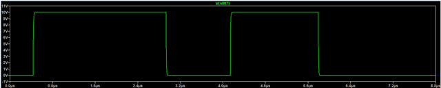
Does anyone have any experience or code that I can use for double pulse generation for the purpose of double-pulse testing? My double pulse code should also be able to vary with different time periods (i.e if I want my t1 to change to 4us, the oscilloscope should also reflect the change after debugging).
I would appreciate it a lot if anyone could provide some input where I went wrong or help me to make the changes to my code. Thanks in advance!
#include "DSP2833x_Device.h"
#include "DSP2833x_Examples.h"

//================== User-adjustable: pick your EPWM and GPIO ==================
#define USE_EPWM1A_GPIO0   1   // Set 1 to route EPWM1A to GPIO0 (JTAG-friendly boards)
#define SYSCLK_HZ          150000000UL   // F28335 default after InitSysCtrl() (150 MHz)
#define TBCLK_DIV          1             // TBCLK = SYSCLK / (HSPCLKDIV*CLKDIV). We set both to /1.
#define TBCLK_HZ           (SYSCLK_HZ / TBCLK_DIV)

// Convert microseconds to TBCLK ticks (rounded)
static inline Uint32 us_to_ticks(float us)
{
    float ticks = (us * (float)TBCLK_HZ) / 1e6f;
    if (ticks < 1.0f) ticks = 1.0f;
    return (Uint32)(ticks + 0.5f);
}

//================== Double-pulse times (change as you like) ===================
// initial low delay, first high, low gap, second high
volatile float t_pre_us = 2.0f;   // example: 2.0 us "quiet" before t1 starts
volatile float t1_us    = 2.5f;   // first high width
volatile float t2_us    = 1.5f;   // low gap
volatile float t3_us    = 1.5f;   // second high width

//================== State machine ==================
typedef enum {
    DP_EDGE0_PRE = 0,   // at t_pre: force HIGH
    DP_EDGE1_END,       // at t_pre+t1: force LOW
    DP_EDGE2_START,     // at t_pre+t1+t2: force HIGH
    DP_EDGE3_END,       // at t_pre+t1+t2+t3: force LOW and stop
    DP_DONE
} dp_state_e;

volatile dp_state_e dp_state = DP_DONE;
volatile Uint32 t_pre_ticks, t1_ticks, t2_ticks, t3_ticks, total_ticks;

// Forward decl
__interrupt void epwm1_isr(void);

static void route_gpio_epwm1a(void)
{
#if USE_EPWM1A_GPIO0
    EALLOW;
    GpioCtrlRegs.GPAMUX1.bit.GPIO0 = 1;  // 1 = EPWM1A
    GpioCtrlRegs.GPADIR.bit.GPIO0  = 1;
    EDIS;
#else
    // If you prefer GPIO1 (EPWM1A), uncomment:
    // EALLOW;
    // GpioCtrlRegs.GPAMUX1.bit.GPIO1 = 1;
    // GpioCtrlRegs.GPADIR.bit.GPIO1  = 1;
    // EDIS;
#endif
}

static void epwm1_setup_for_double_pulse(void)
{
    // Compute ticks from the (possibly modified) microsecond values
    t_pre_ticks  = us_to_ticks(t_pre_us);
    t1_ticks     = us_to_ticks(t1_us);
    t2_ticks     = us_to_ticks(t2_us);
    t3_ticks     = us_to_ticks(t3_us);
    total_ticks  = t_pre_ticks + t1_ticks + t2_ticks + t3_ticks;

    // Time-base clock prescalers -> /1 so TBCLK = SYSCLK
    EALLOW;
    SysCtrlRegs.PCLKCR0.bit.TBCLKSYNC = 0; // stop TBCLK while we configure
    EDIS;

    EPwm1Regs.TBCTL.all = 0;
    EPwm1Regs.TBCTL.bit.CTRMODE   = TB_COUNT_UP;   // up count one-shot frame
    EPwm1Regs.TBCTL.bit.HSPCLKDIV = TB_DIV1;
    EPwm1Regs.TBCTL.bit.CLKDIV    = TB_DIV1;

    EPwm1Regs.TBCTR  = 0;                // start at 0
    EPwm1Regs.TBPRD  = total_ticks + 4;  // a touch of margin beyond last edge

    // No automatic AQ actions on compare; we'll software-force in ISR.
    EPwm1Regs.AQCTLA.all = 0;

    // Start LOW
    EPwm1Regs.AQCSFRC.bit.CSFA = AQ_CLEAR;  // force low

    // First interrupt will be at CMPA-up == t_pre
    EPwm1Regs.CMPA.half.CMPA = t_pre_ticks;

    // Enable interrupt on CMPA-up; fire every event
    EPwm1Regs.ETSEL.bit.INTSEL = ET_CTRU_CMPA;  // INT on up-count CMPA match
    EPwm1Regs.ETSEL.bit.INTEN  = 1;
    EPwm1Regs.ETPS.bit.INTPRD  = ET_1ST;        // interrupt on every event

    // Clear any stale flags
    EPwm1Regs.ETCLR.bit.INT = 1;

    EALLOW;
    SysCtrlRegs.PCLKCR0.bit.TBCLKSYNC = 1; // restart TBCLKs
    EDIS;

    dp_state = DP_EDGE0_PRE;
}

static void pie_enable_epwm1_isr(void)
{
    EALLOW;
    PieVectTable.EPWM1_INT = &epwm1_isr;
    EDIS;

    PieCtrlRegs.PIECTRL.bit.ENPIE = 1;
    PieCtrlRegs.PIEIER3.bit.INTx1 = 1;  // ePWM1 INT
    IER |= M_INT3;                      // CPU int group 3
    EINT;  // Enable Global interrupt INTM
    ERTM;  // Enable realtime DBGM
}

void start_double_pulse(void)
{
    // Reset and configure EPWM1 for a fresh one-shot sequence
    epwm1_setup_for_double_pulse();
    // EPWM starts counting immediately (TBCLKSYNC=1), ISR will drive edges
}

__interrupt void epwm1_isr(void)
{
    switch (dp_state)
    {
        case DP_EDGE0_PRE:
            // t = t_pre: go HIGH, arm next edge at t_pre + t1
            EPwm1Regs.AQCSFRC.bit.CSFA = AQ_SET;  // force high
            EPwm1Regs.CMPA.half.CMPA   = t_pre_ticks + t1_ticks;
            dp_state = DP_EDGE1_END;
            break;

        case DP_EDGE1_END:
            // t = t_pre + t1: go LOW, arm next edge at + t2
            EPwm1Regs.AQCSFRC.bit.CSFA = AQ_CLEAR;  // force low
            EPwm1Regs.CMPA.half.CMPA   = t_pre_ticks + t1_ticks + t2_ticks;
            dp_state = DP_EDGE2_START;
            break;

        case DP_EDGE2_START:
            // t = t_pre + t1 + t2: go HIGH, arm final edge at + t3
            EPwm1Regs.AQCSFRC.bit.CSFA = AQ_SET;  // force high
            EPwm1Regs.CMPA.half.CMPA   = t_pre_ticks + t1_ticks + t2_ticks + t3_ticks;
            dp_state = DP_EDGE3_END;
            break;

        case DP_EDGE3_END:
            // t = total: go LOW and STOP everything
            EPwm1Regs.AQCSFRC.bit.CSFA = AQ_CLEAR;    // final low
            EPwm1Regs.ETSEL.bit.INTEN  = 0;           // no more INTs

            // Freeze the counter so the frame is one-shot and done.
            EPwm1Regs.TBCTL.bit.CTRMODE = TB_FREEZE;
            dp_state = DP_DONE;
            break;

        default:
            break;
    }

    EPwm1Regs.ETCLR.bit.INT = 1;   // ack module INT flag
    PieCtrlRegs.PIEACK.all = PIEACK_GROUP3;
}

//================== Typical C2000 startup ==================
void main(void)
{
    InitSysCtrl();       // 150 MHz, enable peripheral clocks
    DINT;
    InitPieCtrl();
    IER = 0;
    IFR = 0;
    InitPieVectTable();

    // Route EPWM1A pin
    InitGpio();
    route_gpio_epwm1a();

    // Make sure EPWM clock is on
    EALLOW;
    SysCtrlRegs.PCLKCR1.bit.EPWM1ENCLK = 1;
    EDIS;

    pie_enable_epwm1_isr();

    // ---- START THE DOUBLE PULSE ----
    // Set your times (us). You can change these before calling start_double_pulse(). !!!THIS PART TO CHANGE YOUR PULSE TIMINGS!!!
    t_pre_us = 2.0f;   // initial low delay
    t1_us    = 2.5f;   // first high
    t2_us    = 1.5f;   // low gap
    t3_us    = 1.5f;   // second high

    start_double_pulse();

    // Idle here; the ISR will run four times to produce the sequence, then stop.
    for(;;) { asm(" NOP"); }
}
