This thread has been locked.

If you have a related question, please click the "Ask a related question" button in the top right corner. The newly created question will be automatically linked to this question.

TMS320F28P650SK: PLL initialization issue

Part Number: TMS320F28P650SK
Other Parts Discussed in Thread: C2000WARE

Hi Champs,

I ask this for my customer, now they meet below issue when development. We are using the bit fields example code. 

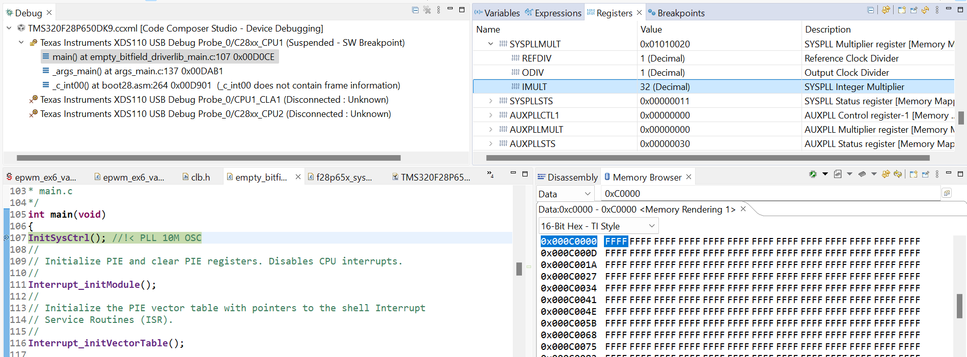
1.Why do the SYSPLLMULT registers have values before main() runs? I saw in the TRM that their reset value is 0. When are these values written to the registers? Below is the display from my Launchpad. The register values read on the customer's board are IMULT=40, REFDIV=1, ODIV=2, which is the same configuration as when using INTOSC. 

image.png

2. Since the SYSPLLMULT register has a value before the PLL is initialized by below code

image.png

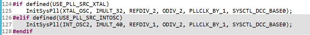
, and the customer is using an external 10MHz XTAL, if the customer uses the same IMULT, ODIV and REFDIV as the internal oscillator, it will cause the code to fail to update the oscillator source to XTAL. 

This is because in InitSysPll() there is a judgment as below:

image.png

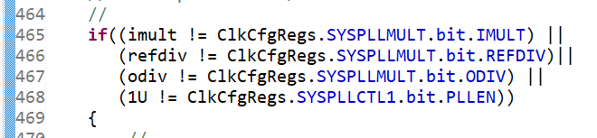
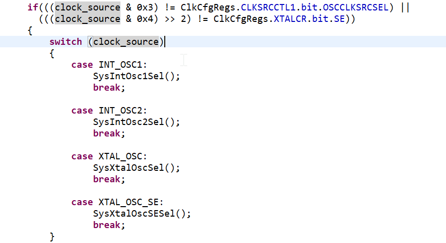
If all the values that need to be checked inside if() are the same as the values currently set by the customer, then the contents inside if() will be skipped and else() will be executed directly. But switch the clock_source code is inside if(). This causes the clock_source switch to fail. 

image.png

3. To avoid the issues mentioned above, customer tried changing IMULT=60, REFDIV=1, ODIV=3. The customer's XTAL is 10MHz. It seems that the customer's configuration meets the requirements, but the customer found that if he uses this configuration, his code output becomes uncontrollable.

image.png

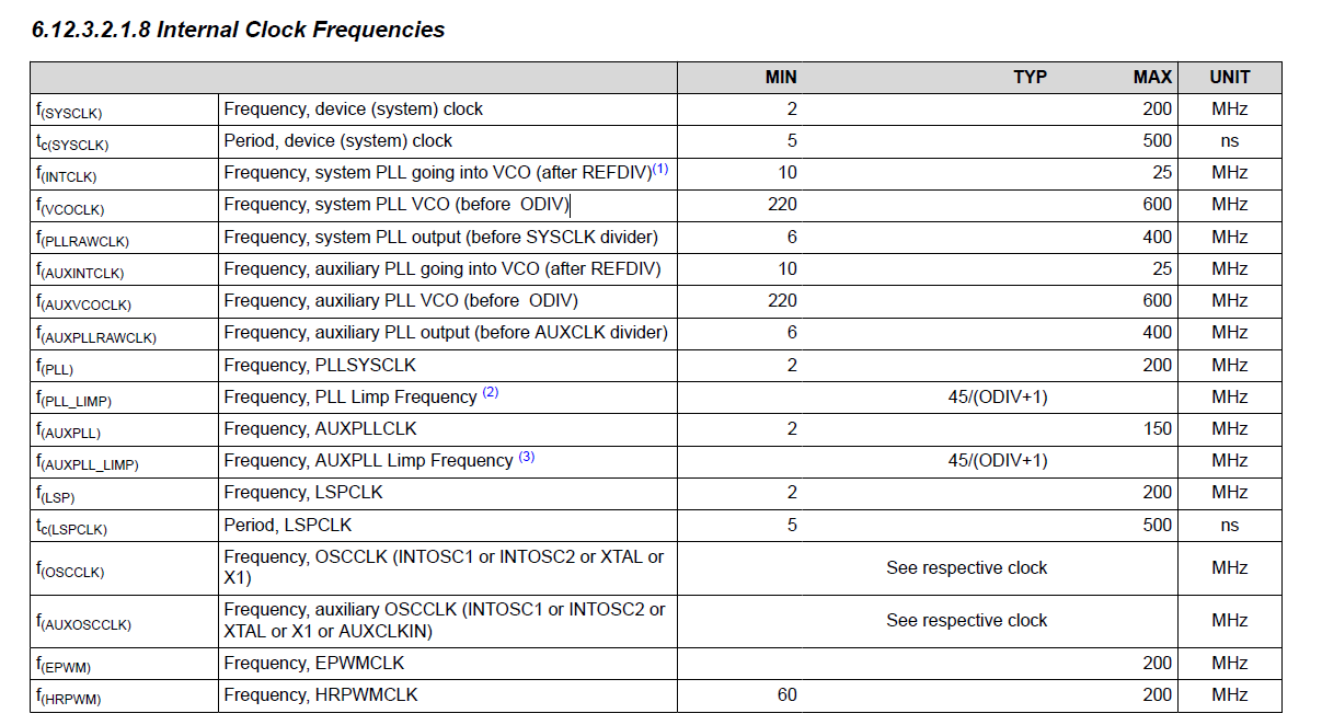
However, if he changes back to IMULT=40, REFDIV=1, ODIV=2 and then manually adds SysXtalOscSel() to switch the clock source to XTAL, the problem disappears. 

Customer want to know why IMULT=60, REFDIV=1, ODIV=3 will have issue.


Could you please help to check this? Thanks!

Best regards,

Julia

  • Hello,

    I will take a look and reply in timely manner.

  • Hi Stevan,

    Is there any update? Thanks!

    Best regards,

    Julia

  • Hi Julia,

    Did you check and tried to run some of the PLL C2000Ware example codes? Also, please refer to the spec tables for multipliers and clock frequencies in Data sheet and TRM. If your multiplier is out of range, the output would not be stable anymore.

  • Hi Stevan,

    Now I have already used bitfields example code and it already has PLL configuration, and will have this issue. Is there any other PLL example?

    3. To avoid the issues mentioned above, customer tried changing IMULT=60, REFDIV=1, ODIV=3. The customer's XTAL is 10MHz. It seems that the customer's configuration meets the requirements, but the customer found that if he uses this configuration, his code output becomes uncontrollable.

    And when IMULT=60, REFDIV=1, ODIV=3 and XTAL=10MHz, I think this meets the datasheet specifications, and I also added the images required by the manual earlier. However, the customer's current test results show that this configuration occasionally fails.

    Thanks!

    Best regards,

    Julia

  • Hi Stevan,

    Is there any update? Thanks!

    Best regards,

    Julia

  • Hi Julia,

    Are you using controlCard or LaunchPad for tests?

  • Hi Stevan,

    I use LaunchPad and you can check below video. You can see that when I connect to CPU1, SYSPLLMULT has a value, and clicking CPU reset does not clear this value. After I load the .out file, you can see that this value is being updated. In short, the initial value of this SYSPLLMULT register is not 0. You should be able to reproduce this if you test it with code.

    Video is in below link:

    https://tidrive.ext.ti.com/u/h5zNsFOczQ-VnM23/fc2e4f8c-4b66-4130-98d6-388dc0523c29?l

    c^G6v7Aw

    And customer still want to check this question. Their XTAL is 10MHz.

    Customer want to know why IMULT=60, REFDIV=1, ODIV=3 will have issue.


    Thanks!

    Best regards,

    Julia

    1. Your assumption about the function line no. 465 in f28p65x_sysctrl.c is correct. The way code is written now, it would skip the PLL clk configuration (switch clock source) and it would start-up with inherited  PLL initialization and registers based on Boot-ROM programmed code.
    2. I took another look at your coefficients, and these coefficients would not work based on the Internal clock frequencies table from TRM that you have attached.

    Please tell them to refer to the Figure 3-10 from TRM

    Based on this diagram with REFDIV = 1, it would give INTCLK = 10MHZ /  (1+1) = 5MHz which is below required range. The minimum of INTCLK should be at least 10MHz. After reviewing the Figure it should be clear to them, I assume they did not know they should add plus 1 for REFDIV and ODIV.