This thread has been locked.

If you have a related question, please click the "Ask a related question" button in the top right corner. The newly created question will be automatically linked to this question.

TMS320F28075: NC pin level

Part Number: TMS320F28075

Hi BU experts,

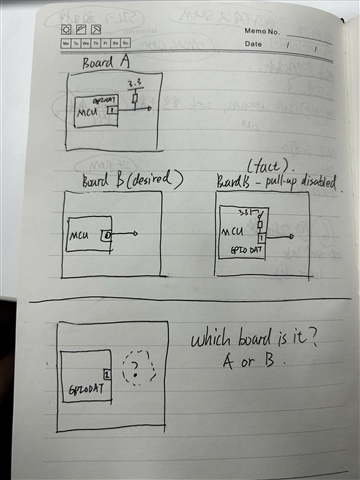
My customer is using a particular NC gpio to distinguish two version of the board. On version A, this GPIO is NC, in version B, the GPIO is pulled up. 

However, when they read the GPIO on version A, the GPIODAT is 1, even with pull-up disalbed. In this way, they can not distinguish the version by this GPIO.

Is there any thing they can do to distinguish the two version of the Board? The GPIO connection is the only differences in these two version and the hardware design is fixed.

Regards,

Hang

  • Hi,

    Can you clarify what is meant by NC gpio ?

    n version A, this GPIO is NC, in version B, the GPIO is pulled up.

    Version B and A are different version of hardware design boards ? Can you make sure GPIO which is NC Its default state is not high ?

    Otherwise it should not read high.

    Thanks

  • Hi Prathan,

    NC gpio means the gpio connects to nothing on the board.

    When probing the NC gpio with multimeter, the voltage level is low and the GPIODAT is 0. When removing the probe, the GPIODAT is high, we assume the level is high.

    I'll put the question in another way.

    There are two board, the only differences on the two board are one GPIO, on board A, the GPIO connects to nothing. on board B, GPIO connects to pull-up resisters. Now, how to distinguish these two boards by software only?

    Regards,

    Hang

  • Two boards can be distinguished by UID number

    Thanks.

  • Hi Prathan,

    Sorry for the confusion, by "two board" I mean "two types of board", the two types of board share same device part number and customer do no track the unqiue ID of the device during manufacture. There for, looking at the ID can not know which board the device is installed on.

    Regards,

    Hang 

  • Okay thanks for clarifying.

    GPIO seems to be correct way to identify system board level changes from the MCU side. When GPIO is pulled up high externally MCU should read the GPIO state correctly, unless the GPIO config are not correctly done.

    Confirm following things - Is GPIO configured as input pin from MCU side, disable internal pull-up and confirm, Is it pulled up high on the system board, configure the GPIO as push-pull mode, Is the Pin mux option correctly configured to GPIO functionality ?

    GPIO reading state should be fairly straightforward given the Pin config are correctly done, I would suggest you try two different pins on the boards.

    Thanks

  • Hi Prarthan

    Is GPIO configured as input pin from MCU side, disable internal pull-up and confirm

    Yes, It is configured as input and pull-up disable. It's not pulled high on system board. The GPIO is configured to GPIO functionality.

    GPIO reading state should be fairly straightforward given the Pin config are correctly done

    The GPIO reading state is correct, there are no "error" reading the GPIO, we are just looking for a way to tell the difference of the two board. Like the below pictures shows, the only difference between board A and B is a external pull-up on a GPIO.

    We expect that when reading the GPIO, Board A returns 1 and board B returns 0, so that we can know which board it is by reading the GPIO.

    However, the truth is on board B we still get a 1 when reading the GPIO, even with internal pull-up disabled.

    In this case, how can we know which board is it by software?

  • Hi,

    It is very unlikely that the GPIODAT is being read as 1 even when its state is not High (either pulled up high externally or internally Pulled up).

    The corresponding bit in the data register reflects the current state of the pin after qualification hence if the GPIO config are correct then GPIODAT register bit for that pin should read correct value.

    Thanks