This thread has been locked.

If you have a related question, please click the "Ask a related question" button in the top right corner. The newly created question will be automatically linked to this question.

TMS320F28P659DK-Q1: MCAN Receive Issue on F28P65x

Part Number: TMS320F28P659DK-Q1

Hi Team ,

I am currently testing the MCAN receive example (mcan_ex4_receive)  on the F28P65x device. The setup involves CAN communication between the F28P65x and a Xilinx Zynq-7000 board.

The transmit path has been successfully verified — messages sent from the F28P65x are received correctly on the Zynq-7000, confirmed using candump  so the hardware connection is known to be good.

However, when I run the receive example (mcan_ex4_receive) , and send a CAN message from the Zynq using:
cansend can0 444#1122

the receive interrupt is not being triggered. I have placed a counter inside the ISR to monitor the number of received messages, but the counter value does not increment (verified through the expression window in CCS).

Could you please provide your insights or recommendations on possible causes or additional checks to perform?

Thank you for your support.

Best regards,
Nigesh

  • Hi Nigesh,

    Thanks for describing the situation here. Can you provide the example.syscfg and main.c files used?

    Can you provide additional details on the function "cansend can0 444#1222"?

    Are you expecting a Standard ID or Extended ID? Are your RX Filters properly configured to accept the appropriate MSG ID objects?

    Are you using MCAN RX Buffer or FIFO structures for storing the accepted message (and in turn, triggering the associated receive interrupt)?

    Are both controllers configured with matching bit timing parameters?

    If any of these configurations are incorrect, then the messages on the CAN bus (sent by the Zynq-7000), won't be accepted by the F28P65x MCAN controller, the interrupt won't be triggered, and the counter value won't be incremented.

    Best Regards,

    Zackary Fleenor

  • Hi Zackary,

    One important note before proceeding — I am trying to receive Classic CAN messages on the F28P65x using the MCAN.


    Can you provide the example.syscfg and main.c files used? 

    • I’m using the standard example code provided with the SDK. The .syscfg file has not been modified. For reference, I’ve attached the main.c file below.


    #include "driverlib.h"
    #include "device.h"
    #include "inc/stw_types.h"
    #include "inc/stw_dataTypes.h"
    #include <string.h>
    
    //
    // Defines.
    //
    #define NUM_OF_MSG                      (1U)
    #define MCAN_STD_ID_FILTER_NUM          (1U)
    #define MCAN_EXT_ID_FILTER_NUM          (0U)
    #define MCAN_FIFO_0_NUM                 (0U)
    #define MCAN_FIFO_0_ELEM_SIZE           (MCAN_ELEM_SIZE_8BYTES)
    #define MCAN_FIFO_1_NUM                 (0U)
    #define MCAN_FIFO_1_ELEM_SIZE           (MCAN_ELEM_SIZE_8BYTES)
    #define MCAN_RX_BUFF_NUM                (10U)
    #define MCAN_RX_BUFF_ELEM_SIZE          (MCAN_ELEM_SIZE_8BYTES)
    #define MCAN_TX_BUFF_SIZE               (0U)
    #define MCAN_TX_FQ_SIZE                 (0U)
    #define MCAN_TX_BUFF_ELEM_SIZE          (MCAN_ELEM_SIZE_8BYTES)
    #define MCAN_TX_EVENT_SIZE              (0U)
    
    //
    //  Defining Starting Addresses for Message RAM Sections,
    //  (Calculated from Macros based on User defined configuration above)
    //
    #define MCAN_STD_ID_FILT_START_ADDR     (0x0U)
    #define MCAN_EXT_ID_FILT_START_ADDR     (MCAN_STD_ID_FILT_START_ADDR + ((MCAN_STD_ID_FILTER_NUM * MCANSS_STD_ID_FILTER_SIZE_WORDS * 4U)))
    #define MCAN_FIFO_0_START_ADDR          (MCAN_EXT_ID_FILT_START_ADDR + ((MCAN_EXT_ID_FILTER_NUM * MCANSS_EXT_ID_FILTER_SIZE_WORDS * 4U)))
    #define MCAN_FIFO_1_START_ADDR          (MCAN_FIFO_0_START_ADDR + (MCAN_getMsgObjSize(MCAN_FIFO_0_ELEM_SIZE) * 4U * MCAN_FIFO_0_NUM))
    #define MCAN_RX_BUFF_START_ADDR         (MCAN_FIFO_1_START_ADDR + (MCAN_getMsgObjSize(MCAN_FIFO_1_ELEM_SIZE) * 4U * MCAN_FIFO_1_NUM))
    #define MCAN_TX_BUFF_START_ADDR         (MCAN_RX_BUFF_START_ADDR + (MCAN_getMsgObjSize(MCAN_RX_BUFF_ELEM_SIZE) * 4U * MCAN_RX_BUFF_NUM))
    #define MCAN_TX_EVENT_START_ADDR        (MCAN_TX_BUFF_START_ADDR + (MCAN_getMsgObjSize(MCAN_TX_BUFF_ELEM_SIZE) * 4U * (MCAN_TX_BUFF_SIZE + MCAN_TX_FQ_SIZE)))
    
    
    //
    // Global Variables.
    //
    
    volatile uint8_t count = 0;
    volatile uint32_t checkintr = 0;
    int32_t     error = 0;
    MCAN_RxBufElement rxMsg[NUM_OF_MSG], rxMsg1;
    int32_t loopCnt = 0U;
    
    
    //
    // Function Prototype.
    //
    static void MCANConfig(void);
    static void MCANIntrConfig(void);
    __interrupt void MCANIntr1ISR(void);
    
    void main()
    {
        int i = 0;
        volatile uint32_t mode = 0U;
        uint32_t dataBytes = 64;
    
        //
        // Initialize device clock and peripherals
        //
        Device_init();
    
        //
        // Initialize GPIO and unlock the GPIO configuration registers
        //
        Device_initGPIO();
    
        //
        // Configure the divisor for the MCAN bit-clock
        //
        SysCtl_setMCANClk(SYSCTL_MCANA, SYSCTL_MCANCLK_DIV_5);
    
        //
        // ISR Configuration.
        //
        MCANIntrConfig();
    
        //
        // Configure GPIO pins for MCANTX/MCANRX operation
        //
    //    GPIO_setPinConfig(DEVICE_GPIO_CFG_MCANRXA);
    //    GPIO_setPinConfig(DEVICE_GPIO_CFG_MCANTXA);
    
        //mcan STB pin
        GPIO_setPadConfig(3,GPIO_PIN_TYPE_PULLUP);
        GPIO_writePin(3,0);
        GPIO_setPinConfig(GPIO_3_GPIO3);
        GPIO_setDirectionMode(3,GPIO_DIR_MODE_OUT);
    
        GPIO_setPinConfig(GPIO_4_MCANA_TX);
        GPIO_setPinConfig(GPIO_5_MCANA_RX);
    
        //
        // Initialize message to receive
        //
        rxMsg[loopCnt].id = 0U;
        rxMsg[loopCnt].rtr = 0U;
        rxMsg[loopCnt].xtd = 0U;
        rxMsg[loopCnt].esi = 0U;
        rxMsg[loopCnt].rxts = 0U;   // Rx Timestamp
        rxMsg[loopCnt].dlc = 0U;
        rxMsg[loopCnt].brs = 0U;
        rxMsg[loopCnt].fdf = 0U;
        rxMsg[loopCnt].fidx = 0U;   // Filter Index
                                    // (of matching Rx acceptance filter element)
        rxMsg[loopCnt].anmf = 0U;   // Accepted Non-matching Frame
    
        for(i = 0; i < dataBytes; i++)  // Initialize receive buffer to 0
        {
            rxMsg[loopCnt].data[i]  = 0;
        }
    
        //
        // Configure the MCAN Module.
        //
        MCANConfig();
    
        //
        // Enable Interrupts.
        //
        MCAN_enableIntr(MCANA_DRIVER_BASE, MCAN_INTR_MASK_ALL, 1U);
    
        //
        // Select Interrupt Line.
        //
        MCAN_selectIntrLine(MCANA_DRIVER_BASE, MCAN_INTR_MASK_ALL, MCAN_INTR_LINE_NUM_1);
    
        //
        // Enable Interrupt Line.
        //
        MCAN_enableIntrLine(MCANA_DRIVER_BASE, MCAN_INTR_LINE_NUM_1, 1U);
    
        while(1)
        {
            //
            //  Adding delay of 1 second
            //
            DEVICE_DELAY_US(1000000);
    
            //
            //  Message Handling Code goes here
            //
    
        }
    
        //
        // Stop Application.
        //
        asm("   ESTOP0");
    }
    
    static void MCANConfig(void)
    {
        MCAN_InitParams initParams;
        MCAN_MsgRAMConfigParams    msgRAMConfigParams;
        MCAN_StdMsgIDFilterElement stdFiltelem;
        MCAN_BitTimingParams       bitTimes;
    
        //
        //  Initializing all structs to zero to prevent stray values
        //
        memset(&initParams, 0, sizeof(initParams));
        memset(&msgRAMConfigParams, 0, sizeof(msgRAMConfigParams));
        memset(&stdFiltelem, 0, sizeof(stdFiltelem));
        memset(&bitTimes, 0, sizeof(bitTimes));
    
        //
        // Configure MCAN initialization parameters
        //
        initParams.fdMode            = 0x0U; // FD operation enabled.
        initParams.brsEnable         = 0x0U; // Bit rate switching enabled
    
        //
        // Initialize Message RAM Sections Configuration Parameters
        //
        msgRAMConfigParams.flssa                = MCAN_STD_ID_FILT_START_ADDR;
        // Standard ID Filter List Start Address.
        msgRAMConfigParams.lss                  = MCAN_STD_ID_FILTER_NUM;
        // List Size: Standard ID.
        msgRAMConfigParams.rxBufStartAddr       = MCAN_RX_BUFF_START_ADDR;
        // Rx Buffer Start Address.
        msgRAMConfigParams.rxBufElemSize        = MCAN_RX_BUFF_ELEM_SIZE;
        // Rx Buffer Element Size.
    
        //
        // Initialize Rx Buffer Configuration parameters.
        //
        stdFiltelem.sfid2              = 0x0U; // Standard Filter ID 2.
        // Configuring received frame to be stored in buffer element 0
        stdFiltelem.sfid1              = 0x444U; // Standard Filter ID 1.
        // Confifuring frames with msg ID = 0x4U to be accepted by filter element
        stdFiltelem.sfec               = 0x7U; // Store into Rx Buffer
                                               // configuration of SFT[1:0] ignored
    
        //
        // Initialize bit timings.
        //
        bitTimes.nomRatePrescalar   = 0x3U; // Nominal Baud Rate Pre-scaler
        bitTimes.nomTimeSeg1        = 0x9U; // Nominal Time segment before SP
        bitTimes.nomTimeSeg2        = 0x8U; // Nominal Time segment after SP
        bitTimes.nomSynchJumpWidth  = 0x8U; // Nominal SJW
        bitTimes.dataRatePrescalar  = 0x1U; // Data Baud Rate Pre-scaler
        bitTimes.dataTimeSeg1       = 0x9U; // Data Time segment before SP
        bitTimes.dataTimeSeg2       = 0x8U; // Data Time segment after SP
        bitTimes.dataSynchJumpWidth = 0x8U; // Data SJW
    
        //
        // Wait for memory initialization to happen.
        //
        while(FALSE == MCAN_isMemInitDone(MCANA_DRIVER_BASE))
        {
        }
    
        //
        // Put MCAN in SW initialization mode.
        //
        MCAN_setOpMode(MCANA_DRIVER_BASE, MCAN_OPERATION_MODE_SW_INIT);
    
        //
        // Wait till MCAN is not initialized.
        //
        while (MCAN_OPERATION_MODE_SW_INIT != MCAN_getOpMode(MCANA_DRIVER_BASE))
        {}
    
        //
        // Initialize MCAN module.
        //
        MCAN_init(MCANA_DRIVER_BASE, &initParams);
    
        //
        // Configure Bit timings.
        //
        MCAN_setBitTime(MCANA_DRIVER_BASE, &bitTimes);
    
        //
        // Configure Message RAM Sections
        //
        MCAN_msgRAMConfig(MCANA_DRIVER_BASE, &msgRAMConfigParams);
    
        //
        // Configure Standard ID filter element
        //
        MCAN_addStdMsgIDFilter(MCANA_DRIVER_BASE, 0U, &stdFiltelem);
    
        //
        // Take MCAN out of the SW initialization mode
        //
        MCAN_setOpMode(MCANA_DRIVER_BASE, MCAN_OPERATION_MODE_NORMAL);
    
        while (MCAN_OPERATION_MODE_NORMAL != MCAN_getOpMode(MCANA_DRIVER_BASE))
        {
    
        }
    }
    
    //
    // This function will configure X-BAR for MCAN interrupts.
    //
    static void MCANIntrConfig(void)
    {
    
        Interrupt_initModule();
        Interrupt_initVectorTable();
    
        Interrupt_register(INT_MCANA_1,&MCANIntr1ISR);
        Interrupt_enable(INT_MCANA_1);
    
        Interrupt_enableGlobal();
    
    }
    
    //
    // This is Interrupt Service Routine for MCAN interrupt 1.
    //
    __interrupt void MCANIntr1ISR(void)
    {
        uint32_t intrStatus;
        MCAN_RxNewDataStatus newData;
    
        intrStatus = MCAN_getIntrStatus(MCANA_DRIVER_BASE);
        checkintr = intrStatus;
    
        //
        // Clear the interrupt Status.
        //
        MCAN_clearIntrStatus(MCANA_DRIVER_BASE, intrStatus);
    
        //
        //  Clearing the interrupt lineNum
        //
        MCAN_clearInterrupt(MCANA_DRIVER_BASE, 0x2);
    
        //
        //  Check to see if the interrupt is caused by a message being
        //  received in dedicated RX Buffers
        //
        if((MCAN_INTR_SRC_DEDICATED_RX_BUFF_MSG & intrStatus) == MCAN_INTR_SRC_DEDICATED_RX_BUFF_MSG)
        {
    
            //
            // Read the NewData registers
            //
            MCAN_getNewDataStatus(MCANA_DRIVER_BASE, &newData);
    
            //  If message is received in buffer element 0
            if((newData.statusLow & (1UL << 0U)) != 0)
            {
                MCAN_readMsgRam(MCANA_DRIVER_BASE, MCAN_MEM_TYPE_BUF, 0U,
                              0, &rxMsg1);
    
                rxMsg[loopCnt] = rxMsg1;
                count ++;
            }
    
            //
            //  Clearing the NewData registers
            //
            MCAN_clearNewDataStatus(MCANA_DRIVER_BASE, &newData);
        }
        else
        {
            error++;
    
            //
            //  Interrupt handling for other interrupt sources goes here
            //
    
        }
    
        //
        // Acknowledge this interrupt located in group 9
        //
        Interrupt_clearACKGroup(INTERRUPT_ACK_GROUP9);
    }

    Can you provide additional details on the function "cansend can0 444#1222"? 

    • I used the Linux can-utils tool to transmit the CAN frame with the following command cansend can0 444#1122
    • The F28P65x is configured to receive messages with Message ID 0x444.

    Are you using MCAN RX Buffer or FIFO structures for storing the accepted message (and in turn, triggering the associated receive interrupt)? 

    • I’m using the MCAN RX Buffer for message reception and to trigger the associated receive interrupt.

    Are you expecting a Standard ID or Extended ID? Are your RX Filters properly configured to accept the appropriate MSG ID objects?

    • I am expecting a Standard ID. However, I don’t have a complete understanding of the RX filter configuration. If there are any mistakes in my setup or code, I would appreciate it if you could point them out. Additionally, if there is any document or reference that explains the MCAN configuration parameters and their respective meanings, please share it.

    Are both controllers configured with matching bit timing parameters?

    • Both controllers are configured with matching bit timing parameters — the F28P65x uses the timing settings from mcan.c, and on the Zynq-7000, I’ve set the bitrate using: ip link set can0 type can bitrate 500000


  • Hi Nigesh,

    Thank you for providing this information, this helps quite a bit.

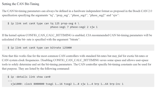
    One thing I would like you to try is rather than rely on the automatic configuration done when using the "bitrate -x" attribute, provide a manual definition of all of the timing parameters to exactly match that of the F28P65x.

    https://www.kernel.org/doc/html/latest/networking/can.html#setting-the-can-bit-timing

    You can also double check the auto calculated parameters using

    ip -details link show can0

    It looks like the MCAN_FIFO Element sizes are set to 8Bytes, but in main(), dataBytes is set to 64. What is the element size and number of data bytes expected on the bus?

    The document below provides a good explanation of how to use the MCAN peripheral and descriptions of the Filter ID and MSG Ram configurations.

    https://www.ti.com/lit/an/spracu9/spracu9.pdf

    Best Regards,

    Zackary Fleenor

  • Hi Fleenor,

    I believe there is no issue with the bitrate configuration on either side. This was verified by transmitting data from the F28P65x using the mcan_ex7_classic_transmit.c example and successfully receiving it on the Zynq-7000 via candump can0 (can utility). The same bitrate settings used in mcan_ex7_classic_transmit are also used in the code currently under test, which I have attached in my previous reply.

    Regarding the element size, since I am using Classic CAN, I am expecting a payload size of 8 bytes, and the RX Buffer element size is configured accordingly.

  • Hi Bala,

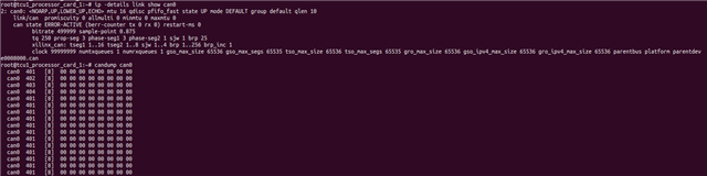
    Can you provide the output from the Zynq-7000 for "ip -details link show can0" in both cases?

    How did you calculate the initial bit timing parameters? Are you using the defaults from the example?

    Best Regards,

    Zackary Fleenor

  • Hi Fleenor,


    1.

    Tx from the f28p65x :


    //
    // Initialize bit timings.
    //
    bitTimes.nomRatePrescalar = 0x3U; // Nominal Baud Rate Pre-scaler
    bitTimes.nomTimeSeg1 = 0x9U; // Nominal Time segment before SP
    bitTimes.nomTimeSeg2 = 0x8U; // Nominal Time segment after SP
    bitTimes.nomSynchJumpWidth = 0x8U; // Nominal SJW


    RX in the f28p65x : 

    //
    // Initialize bit timings.
    //
    bitTimes.nomRatePrescalar = 0x3U; // Nominal Baud Rate Pre-scaler
    bitTimes.nomTimeSeg1 = 0x9U; // Nominal Time segment before SP
    bitTimes.nomTimeSeg2 = 0x8U; // Nominal Time segment after SP
    bitTimes.nomSynchJumpWidth = 0x8U; // Nominal SJW

    2.

    How did you calculate the initial bit timing parameters? Are you using the defaults from the example?

    yes i am using the default bit timing parameters from the example 

  • Hello Bala,

    Thank you for providing this additional information and apologies for delayed response over the holiday break.

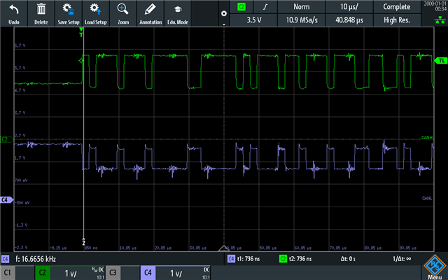
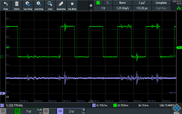
    Are you able to probe the CAN_H/L and MCAN_RX/TX pins for both transmission and receive testing on the F28P65x and provide scope shots of the active communication. I am interested to understand if the data is correctly transmitted on the bus from the Zync. If you have another receiver besides the F28P65x like a second Zync device or a third party USB2CAN Hub, is the data correctly received upon transmission?

    Best Regards,

    Zackary Fleenor

  • Hi Fleenor,

    Please find the scope shot of both CAN_H/L and MCAN_ RX/TX signals below 

    CAN_H and CAN_L : 


    MACN_RX and MCAN_TX : 


    Regarding your question on validating the Zynq transmission:
    Yes, the CAN frame sent from Zynq board A is successfully received by Zynq board B on the same bus (verified using candump can0).


  • Hello Bala,

    Thank you for providing this. The signals look okay from what is shown.

    Are you able to connect and F28P65x to another F28P65x and test the communication between these two without use of a Zynq board?

    It looks like the timing parameters between the Zynq and F28P65x don't line up from what you shared.

    bitrate: 49999 = 50Mbps

    sample point = 0.875

    tq = 250

    propseg = 3

    phaseseg1 = 3 (VS nomTimeSeg1 = 9)

    phaseseg2 = 1 (VS nomTimeSeg2 = 8)

    sjw = 1 (VS nomSynchJumpWidth = 8)

    brp = 26

    ///////////////////////////////////////////////////////////////////////////////////////////////////////////////

    bitTimes.nomRatePrescalar = 0x3U; // Nominal Baud Rate Pre-scaler
    bitTimes.nomTimeSeg1 = 0x9U; // Nominal Time segment before SP
    bitTimes.nomTimeSeg2 = 0x8U; // Nominal Time segment after SP
    bitTimes.nomSynchJumpWidth = 0x8U; // Nominal SJW

    Can you hard code the zynq CAN timing parameters to match that of the F28P65x?

    Best Regards,

    Zackary Fleenor