This thread has been locked.

If you have a related question, please click the "Ask a related question" button in the top right corner. The newly created question will be automatically linked to this question.

TMS320F28377D: Problems with can controller message number 32 (interrupt)

Part Number: TMS320F28377D
Other Parts Discussed in Thread: C2000WARE

Hello,


I am using the TI-TMS320F28377D for a motor drive application, on core 1 I have a standard CAN-Stack and on core 2 I have the motor drive specific software, the two cores exchange information over the IPC.

Everything works well, I can send CAN-messages over the mailbox 1 and I receive new CAN-messages over the mailbox 2.

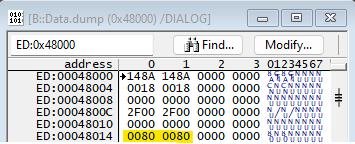
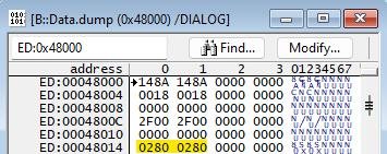
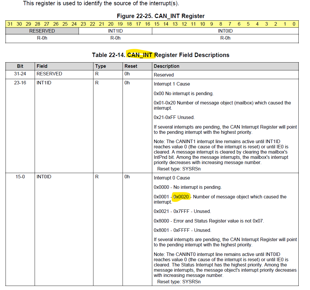
The problem is that I sporadically receive a message in the mailbox 32, but all other receive-mailboxes 3…31 are completely empty (no interrupt pending), how can this happen?

Why does the CAN controller send us a message in the mailbox 32?


image.png

Is this behaviour faulty or a regular process?


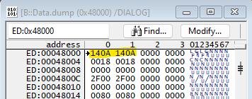
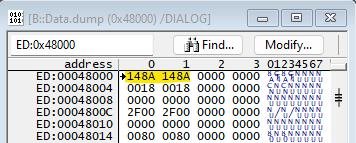
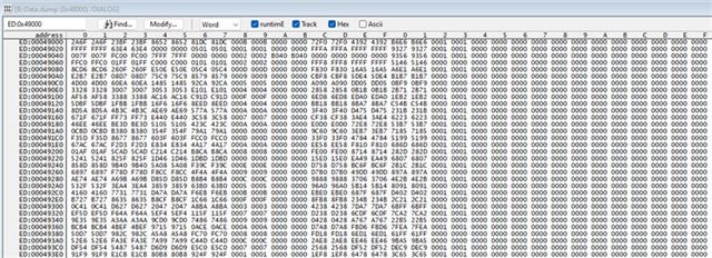
You can see this in the picture below, where I have used one counter for each mailbox, so that when a new message occurs, the counter will be incresed by one.


An additional question, why is interrupt triggeered so often with message number 0?


Thank you for your support.

  • Hi,

    Is the mailbox 32 configured (DIR, ID, MASK,etc)?  If mailbox is not configured, the coming message should not be stored in this mailbox. 

  • Hi,

    The mailbox 32 is configured, 2-32 is configured for rx.

    Why do we have a mailbox jump from 2 -> 32, without processing for example mailbox 3 first.

    And why do we get messages from mailbox 32 overall?

  • Hi Stefan,

    When two CAN mailboxes have the same message ID numbers, the receiving CAN message should be stored in the mailbox with the lower mailbox number. Does mailbox32 have the same settings (msg ID, mask) as the mailbox 2? Is the receiving message (11 msgs saved in #32) stored to both mailbox2 and mailbox32, or just one of them? 

    I also noticed that the number of mailboxes starts from 0x0. The CAN module only supports 32 mailboxes, why do you have 33 mailboxes (0~32)?  

    Which CAN module (A or B) is used by CPU1 and which one is owned by CPU2? You cannot simultaneously access one CAN module from both CPUs

  • Hi QJ,

    In our system, the can stack processing only one msg numer (see CAN_INT register number of message 1-32) at the same time. The received msg is only in one mailbox, either (in our case for rx) 2 or 32. Configured is 1(tx) and 2-32(rx).

    When interrupt (CAN_INT hw register, see description in our previous msg above) signals msg 0, this means no real interrupt pending (no msg). So, we have not really 33 mailboxes, but only 1-32 (see manual too).

    Can handling is done in our application only via cpu1. We are using CAN module A.

    So, the main question is still, why do we got interrupts with msg id 32 (is this a fault?), and not for example msg id 3.

  • we have not really 33 mailboxes, but only 1-32 (see manual too).

    I know there are only 32 mailboxes. I was confused by the name of MB0_Cnt and MB32_Cnt in your snapshot.

    why do we got interrupts with msg id 32 (is this a fault?), and not for example msg id 3.

    I did a CAN RX test on this device, and didn't see this kind of issue. Can you share your code for configuring the CAN message objects? You can check if the mailboxes in message RAM are configured correctly.

    Enable Test mode in CAN_CTL Register, then enable RNA in CAN_Test register:

  • Hello QJ,


    Here is my configuration for CAN message objects:


        # define CAN_LAST_OBJ       32


        /*
         * Initialize message buffers.
         * The control/status word of all message buffers are written
         * as an inactive receive message buffer.
         */


        /* Request for automatic RAM initialization */
        CAN_SET_BIT((can_base_addr + DCAN_CFR), DCAN_CFR_RAMINIT_SET_MSK, DCAN_CFR_RAMINIT_SET_MSK);
        timeout=20000;
        while((CAN_READL(can_base_addr + DCAN_CFR) & DCAN_CFR_RAMINIT_SET_MSK) != 0)
        {/* Wait for RAM initialization complete */
            if(timeout-- == 0)
             {
               perror("timeout: Unable to RAM reset msgbox complete\n");
               return(CO_E_INIT_HARD_RES_ACTIVE);
             }
        }

        for(bN = 1; bN <= CAN_LAST_OBJ; bN++) {


          /* Wait in loop until busy bit is cleared */
          while((CAN_READL(can_base_addr + DCAN_IFCMD(DCAN_IF2_REG)) & DCAN_IFCMD_BUSY));
          /* Clear the MsgVal bit of DCAN_IFARB register */
          CAN_WRITEL(can_base_addr + DCAN_IFARB(DCAN_IF2_REG), 0u);
          /* Set the Arb bit of DCAN_IFCMD register */
          DCAN_CommandRegSet(can_base_addr, (DCAN_IFCMD_ARB | DCAN_IFCMD_WR_RD),
                    bN, DCAN_IF2_REG);

        }


        /*
         * The first tx object is configured as a transmit object
         * with transmit interrupt enabled
         */
         entry.flag = (CAN_DATA_FRAME | CAN_MSG_DIR_RX);
         entry.id = 0;


         /*
          ** Configure a receive message object to accept CAN
          ** frames with standard ID.
         */
         Set_RxObjectConfig(can_base_addr, 0x00, &entry);


    /**
    * \brief   This function will configure a message object in DCAN message RAM
    *          as a receive message object.
    *
    * \param   baseAdd       Base Address of the DCAN Module Registers.
    * \param   canPtr        Pointer to can_msg structure.
    *
    **/
    UNSIGNED8 Set_RxObjectConfig(UNSIGNED32 baseAdd, UNSIGNED32 id_mask, can_msg* canPtr)
    {
    UNSIGNED32 idLen;
    UNSIGNED32 msgIndex;


        msgIndex = CAN_RECEIVE_OBJ;


        idLen = (canPtr->flag & CAN_EXT_FRAME) ? DCAN_IFARB_XTD : 0u;


        /* Wait in loop until busy bit is cleared */
        while((CAN_READL(can_base_addr + DCAN_IFCMD(DCAN_IF2_REG)) & DCAN_IFCMD_BUSY));


        /* Use Acceptance mask. */
        /* Clear the UMask bit of DCAN_IFMCTL register */
        CAN_SET_BIT(baseAdd + DCAN_IFMCTL(DCAN_IF2_REG), DCAN_IFMCTL_UMASK, 0u);
        /* Set the UMask bit of DCAN_IFMCTL register with the user sent value */
        CAN_SET_BIT(baseAdd + DCAN_IFMCTL(DCAN_IF2_REG), DCAN_IFMCTL_UMASK, DCAN_IFMCTL_UMASK);
        /* Configure the DCAN mask registers for acceptance filtering. , MXtd check enable, ID check all bits */
        CAN_SET_BIT(baseAdd + DCAN_IFMSK(DCAN_IF2_REG), 0xFFFFFFFF, (id_mask | DCAN_IFMSK_MXTD));
        /* set direction receive */
        CAN_SET_BIT(baseAdd + DCAN_IFARB(DCAN_IF1_REG), DCAN_IFARB_DIR, 0u);


        /* Set arbitration register for receive interface */
        if(idLen == DCAN_IFARB_XTD)
        {/* ext. Id */
            /* Dir=0,xtd=1, 29bit Id  used of the frame to be received */
          CAN_SET_BIT(baseAdd + DCAN_IFARB(DCAN_IF2_REG), (DCAN_IFARB_MSK | DCAN_IFARB_XTD), (canPtr->id | DCAN_IFARB_XTD));
        }
        else
        {/* standard ID */
          canPtr->id <<= DCAN_STD_ID_SHIFT;
          /* Dir=0, xtd=0, 11bit Id  used of the frame to be received */
          CAN_SET_BIT(baseAdd + DCAN_IFARB(DCAN_IF2_REG), (DCAN_IFARB_MSK | DCAN_IFARB_XTD), canPtr->id);
        }


        /* Set the message valid bit */
        CAN_SET_BIT(baseAdd + DCAN_IFARB(DCAN_IF2_REG), DCAN_IFARB_MSGVAL, DCAN_IFARB_MSGVAL);


        /* Enable the receive interrupt for the message object */
        CAN_SET_BIT(baseAdd + DCAN_IFMCTL(DCAN_IF2_REG), DCAN_IFMCTL_RXIE, DCAN_IFMCTL_RXIE);


        /* Enable the FIFO end of block */
        CAN_SET_BIT(baseAdd + DCAN_IFMCTL(DCAN_IF2_REG), DCAN_IFMCTL_EOB, DCAN_IFMCTL_EOB);


        /* Check for the message valid status for receive objects */
        while((DCAN_MsgValidStatusGet(baseAdd, msgIndex)) && (msgIndex <= CAN_LAST_OBJ))
        {
            msgIndex++;
            if(msgIndex > CAN_LAST_OBJ)
            {
              return CO_E_MEM;
            }
        }


        /* Configure the command register */
        DCAN_CommandRegSet(baseAdd, (DCAN_IFCMD_CONTROL | DCAN_IFCMD_ARB | DCAN_IFCMD_MASK | DCAN_IFCMD_WR_RD),
                   msgIndex, DCAN_IF2_REG);


        return CO_OK;
    }

  • Any news or findings? Do you need further information from my side? Please let me know.

  • Hi Stefan,

    No, I don't fully understand your code. Why don't you use the APIs from C2000Ware? Did you check the configurations of the message objects in message RAM in debug mode?

  • Hi QJ,

    We have bought a fully can open stack, which includes also hardware initialization. If you need in this issue further information, please let me know.

    This is why we not use API from C2000ware.

    Can you explain me in some simple words (for dummies), what debug mode is and what I have to do, to get the necessary information for you. 

  • Hi Stefan,

    In test mode, you can access directly the message RAM. 

    1. Set "TEST" bit of "CAN_CTL" register to enable the TEST mode

    2. Set "RDA" bit of CAN_TEST register to enable the direct access to the message RAM

    I changed two registers directly from the memory browser:

    CTL at 0x48000: 0x1401 -->0x1481 to enable TEST mode 

    TEST at 0x48014: 0x0080 --> 0x0280 to enable RDA

    3. In CCS, open the memory browser

    Teh 1st message object is located starting at offset 0x20, the 2nd message object at 0x40. The last message object (#32) will be written to the very begining starting at 0x00 (offset)


  • Hi QJ,

    Thank you for the detailed information.

    First I set the "TEST" bit of "CAN_CTL" register to enable the TEST mode:


    Afterwards I set the "RDA" bit of CAN_TEST register to enable the direct access to the message RAM:


    The 0x49xxx values are as following (I can only see words with my debugger):


    Do you see here something that is not right or everything is as it should be?

    Do you need more information or can you already tell me why sometimes the messages land in the message box 32?

  • The last screenshot is not clear. I noticed that all the mailbox has two bytes of data (at 0x10, 0x11), is it true? For mailbox 32 (at 0x4900), the RmtEn is set (bit 9 at 0x0E offset). You can check the status and settings of your mailbox 32 using the table below as a reference.