This thread has been locked.

If you have a related question, please click the "Ask a related question" button in the top right corner. The newly created question will be automatically linked to this question.

TMS320F28388D: IGBT On industrial drive development kit triping.

Part Number: TMS320F28388D

Dear support team,

I have ordered Industrial drive development kit from TI for evaluation of PMSM motor control algorithm. I have connected 150V dc to kit and i have slected option to generate 15V required for IGBT driver from this 150V by means of power supply module present on kit. I have also given PWM signlas from control card(TMS320F28388d) but i have observed IGBT is not switching.

I checked voltgae across Vbs-U and BS-U pin i am getting this voltage as 2.8V, while expected voltage is 15V and this is reason why IGBT module is tripping. could anyone tell me why this is happening and how to get rid of this problem.
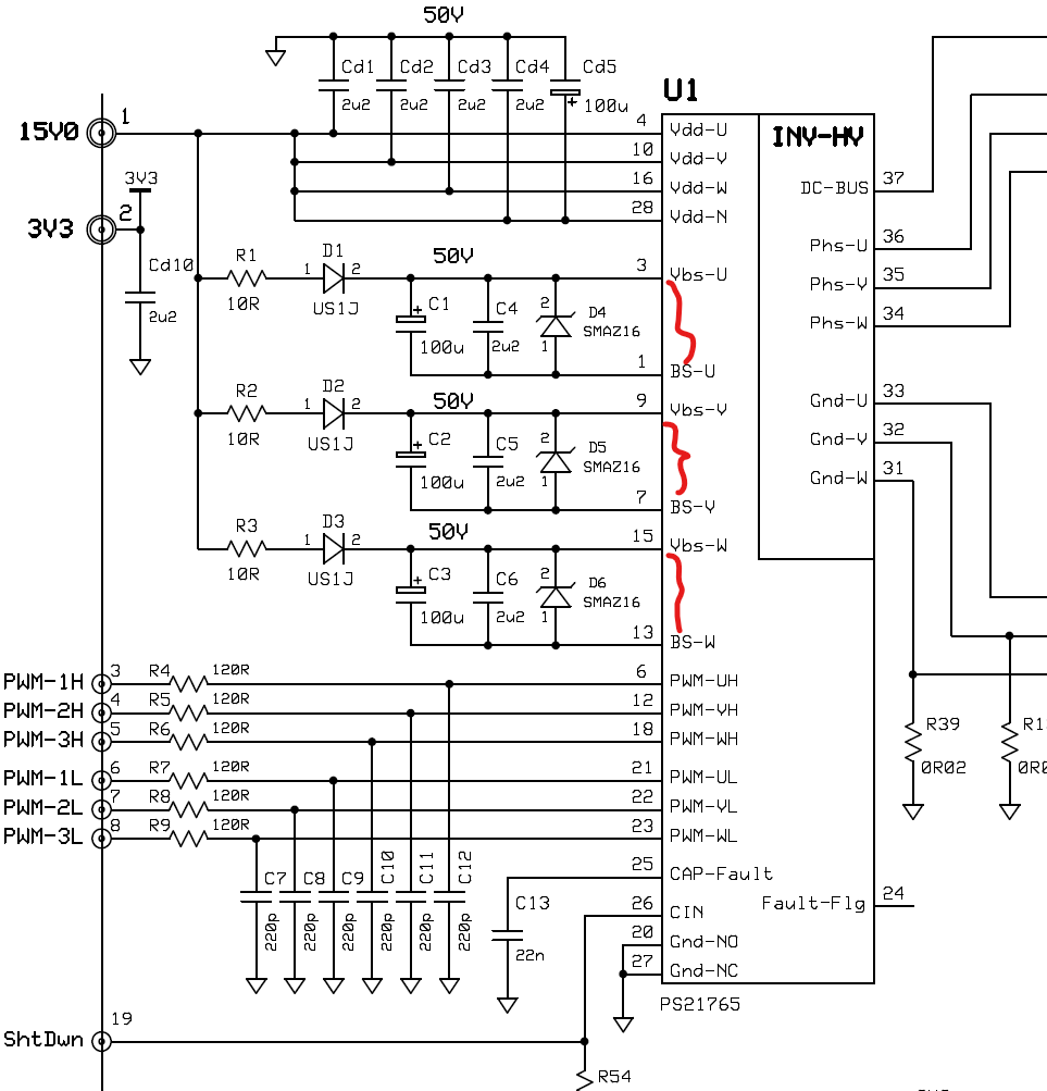
image.png


  • Aniket,

    Are you using example code for this kit or its is your custom code?

    Are you getting main 15V to gnd from main power supply?

    The voltages that you have annotated are bootstrapped from main 15V to generate high side 15V for all top fet. If there is no sufficient pulse for charging the bootstrap cap it won't provide you required voltage.

    Regards,

    Sumit

  • hello Sumit, I am using my code to generate pulses.

    Yes i am getting 15V power supply (I have checked between VddU-Gnd,VddV-gnd,VddW-Gnd, and VddN-Gnd).

    I am switching FETs with 16Khz of frequency and duty is varying in sinusoidal fashion?

    could you please tell me what minimum switching frequency and pulse width of PWM require to charge bootstrapped cap? do I need to follow some special 

    sequence of switching in the beginning to charge the bootstrap cap? shall i try keeping lower MOSFET ON for some time to let bootstrapped cap charge before applying PWM pulses? Do you have any idea about charging time of boostrap cap?

  • Aniket,

    Can you check this kit with our reference code released in MCSDK? You can also refer the code for startup sequence to see how much time lower FET is ON to enable bootstrap voltage. I think this kit should be good enough with as high as 20~30kHz frequency. 16kHz should not be the issue.

    Regards,

    Sumit

  • I am switching FETs with 16Khz of frequency and duty is varying in sinusoidal fashion?

    Adding at least 20V voltage on Vdc-Bus, to measure the voltage and signals between BS and VBS using an oscilloscope with a high voltage differential probe if you want, not using a multimeter. 

    Or check the outputs on Phas-U/V/W using an oscilloscope with a high voltage differential probe.

    could you please tell me what minimum switching frequency and pulse width of PWM require to charge bootstrapped cap? do I need to follow some special 

    Make sure the switching frequency is lower than 20kHz for this power inverter module (PS21765). Please refer to the datasheet of PS21765 for the other specification, like minimum duty, dead time (looks >2us).

    sequence of switching in the beginning to charge the bootstrap cap? shall i try keeping lower MOSFET ON for some time to let bootstrapped cap charge before applying PWM pulses? Do you have any idea about charging time of boostrap cap?

    Yes. It's better to turn on all 3 low-side and turn-off all 3 high-side for some time to  let bootstrapped cap charge. It's an optional to get a better performance, not must do.

    As Sumit mentioned. Please refer to the example codes in motor control SDK to set up and use the kit.