TMS320F28P650DK: Extreme jitter between interrupt trigger and interrupt first instruction

Part Number: TMS320F28P650DK


Hi,

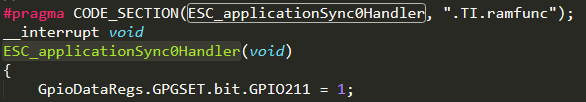
attacched in the below picture is shown the delay, plotted in an istrogram between the arrival of the interrupt trigger (in particular a ECAT SYNC0 signal, routed with the OUTPUT XBAR in a GPIO) and the first istruction be executed inside the ESC_applicationSync0Handler (set a GPIO). 

My question is about the extreme jitter of about 500ns (100 istructions @ 200MHz), can it be consider normal? My problem is not of the delay itself but it not being constant.

Please note that this is the only interrupt active and it's executing from RAM.

image.png

  • Sorry image was not uploaded correctly:

  • Hi Mattia,

    Note the below.

    The steps the CPU goes through when it gets an interrupt are actually as follows:

    The steps take around the below amount of time

    • Clearing the CPU pipeline: ~8 cycles (can be more if CPU is executing a RPT instruction)
    • Context Save: ~8 cycles
    • ISR - x cycles
    • Context Restore: ~8 cycles

    So overall they can expect interrupt overhead should be around 24 cycles (so fairly negligible). 

    Below are some other things they can do to help with tight interrupt timing:

    • Avoid doing (non-inline) function calls inside the ISR. Use direct HWREG accesses to registers
    • Avoid doing any sort of polling/waiting loop inside the ISR - for example don't call a blocking SPI function that will require the CPU to wait
    • Turn compiler optimizations on in the project properties to minimize instructions used
    • Set the HPI compiler pragma for each ISR so that the FPU registers don't need to be pushed onto the stack (this setting saves them in shadow registers instead).
    • Avoid using RPT instruction

    Best Regards,

    Delaney

  • That being said, 100 instructions between the trigger and the ISR execution you are mentioning seems like a lot. I would suggest opening the disassembly window to examine this further by navigating to View >> Disassembly with the debugger connected. This way, you can see if there is some extra code being run at the beginning of the ISR, and also add a breakpoint to the true beginning of the ISR (rather than the C interpreted start).  A context restore won't always take a constant amount of time because it depends on where in the program the CPU is executing when the interrupt comes in. 

    Best Regards,

    Delaney

  • I Delaney,

    thank you for your response. I'll have a look at the ISR instructions. One clarification:

    The steps take around the below amount of time

    • Clearing the CPU pipeline: ~8 cycles (can be more if CPU is executing a RPT instruction)
    • Context Save: ~8 cycles
    • ISR - x cycles
    • Context Restore: ~8 cycles

    About the first two points are you referring to this part of the TRM? 

    Or they are something to sum to this?

    Also i know that context save/restore can take variable time depending on the context, but it can really jump from 250 to 550 ns delay? So 300ns jitter (Sorry in the beginning i wrote 500ns).

  • I have looked at the disassembly, from the beginning of the ISR to the GpioSet istruction there are 24 instructions. So 16 that you mentioned + 24 = 40 -> 200ns. Now in the picture we can see that normally the code ISR is delayed of about 225ns. This is consistent considering also the Gpio set instructions and the actual GPIO dynamic. Still the variation of more than 300ns = 60 instructions is not clear.

  • Hi, I've found the problem. The problem is the auto-generated ECAT stack code, in particular during register access. 

    basically every time that the ESC read a register it disable all interrupts causing the jitter that I've shown you. Since this part causes a delay of even the SYNC0_ISR it seems that there are problems with the ECAT stack.

  • Hi Mattia,

    About the first two points are you referring to this part of the TRM? 

    Yes, these would be the same cycles referred to in the TRM. 

    I see, yes if this portion of the code is disabling interrupts globally (DINT), and an interrupt gets flagged during this time, it will cause some extra delay in the ISR execution. I will loop in the ECAT expert to take a look at this.

    Best Regards,

    Delaney

  • Hi , I think this is more related if something can be done to improve its isr execution not specifically related to ethercat. Will try to include some expert from that domain if something can be done related to that.

  • Hi Kunal, sorry but it appears to me that if the ethercat stack code is causing the ISRs in that specific core to be delayed than the problem is the ethercat stack code itself. If no ethercat stack code is executed than the jitter values are in a more reasonable range (10-40ns)

  • Hi , Yes i have understood that part , Sorry, I didn't mean optimization related in general to any ISR . I meant if some fast interrupt options or preemption related options are available that can be done in that part of code.

  • Some updates?

  • Hi , after talking with an expert , no optimizations are possible since for reading pdi pdo interface we need to disable isr to maintain data integrity.

  • Hi, i can understand the motivation behind this but let me express my concerns. Integrating a peripheral like ethercat that on datasheet guarantees synchronization in order of tens of nS and then discover that due to some implementation decision the ISRs in that core will have an extreme jitter (basically 10-20x the capability of the ethercat sync) will basically remove all the benefits of using such peripheral. As for a matter of clarity maybe updating the ethercat section in the TRM about this delays will be a good idea. In any case for me the matter can now be considered close. Thank you for your support.

  • I agree with Mattia, it looks like being at least not efficient implementation of the ESC peripheral, also causing conflicts with the typical high frequency and very high priority ISRs that usually run on a uC/DSP that use to manage a power converter, as an example.

  • The EtherCAT packet will not come in perfect fixed frequency, mainly due to performance / scheduling limitation of the master node. As a result, EtherCAT is using distributed clock and 3 buffer system to sync all devices on the chain. Although they may have received the packet at different times / timing of the packet have jitter, they will still be in sync from SYNC0 signal.

    If you bring the SYNC0 signal to GPIO pin of F28P65x device, it is perfectly at frequency and have very minimum jitter. The SYNC0 ISR is triggered by this signal, but due to CPU may be doing different things when this SYNC0 ISR trigger comes, there may be some jitter in the time of first C code executed in the ISR. This is not related to the ESC peripheral itself.

    F28P65 is using standard ESC IP from Beckhoff and is certified by ETG.

  • Yes, i agree, the signal muxed on a GPIO will have minimum jitter. But the point that, by the use of DINT, the ECAT stack code itself is disrupting the ISRs inside the core where the ECAT stack is executed. Basically i have to sacrifice one core to execute the ethercat stack if my application cannot allow such jitter. So in the end is not:

    due to CPU may be doing different things when this SYNC0 ISR trigger comes

    It is not doing different things, it is disabling its interrupts to handle the ESC.