This thread has been locked.

If you have a related question, please click the "Ask a related question" button in the top right corner. The newly created question will be automatically linked to this question.

TMS320F28P550SJ: ADC Description mismatch in TRM

Part Number: TMS320F28P550SJ

Hi experts,

I found some descripiton mismatch in f28p55 TRM

In INTPULSEPOS bit, it describes that Interrupt pulse generation occurs at the end of the conversion, 1 cycle prior to the ADC result latching into its result register.

image.png

image.png

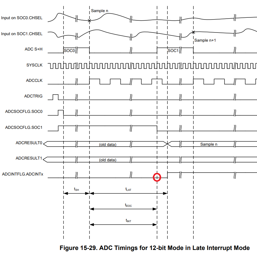
Q1: Should The interrupt signal be triggerred on the red circle?

image.png

image.png

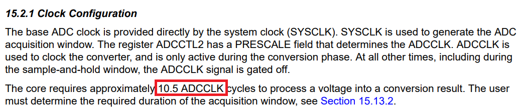
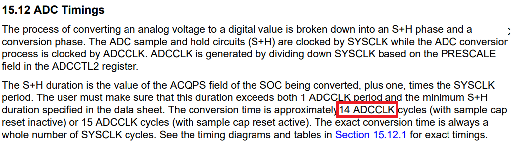
Q2: Which conversion time estimation is correct?

Thanks,

Leo

  • Hello,

    A1: The INTPULSEPOS bit determines whether the ADC interrupt pulse occurs early (at the start of conversion) or late (near the end of conversion).
    In Late Interrupt Mode, the TRM says: “Interrupt pulse generation occurs at the end of the conversion, 1 cycle prior to the ADC result latching into its result register.”
    Looking at Figure 15-29, the red circle is placed just before the ADCRESULT latch update.

    A2: Which conversion time estimation is correct?

    The 10.5 cycles refers to the core conversion phase only (after sample-and-hold ends).

    The 14 cycles likely includes additional overhead, such as: sample capacitor reset, pipeline latency, and possibly rounding up to a safe worst-case estimate.

    Best Regards,

    Masoud