This thread has been locked.

If you have a related question, please click the "Ask a related question" button in the top right corner. The newly created question will be automatically linked to this question.

TMS320F28P650DK: SDFM bit shift table

Part Number: TMS320F28P650DK
Other Parts Discussed in Thread: AMC0336

Hello,

I am trying to configure the SDFM module and I think the table specifying bit shift configuration is wrong:
image.png

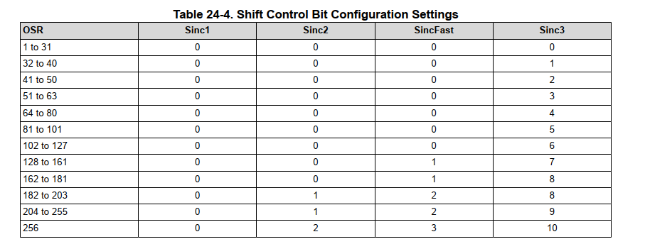
(this is taken from SPRUIZ1B, page 4258)

The setup: I do my sigma-delta measurement with Sinc3 and OSR = 256. I apply the full range of the nominal U_min - U_max to my sigma delta module (AMC0336, about +- 1V) and I watch the result in SDDATA1 (specifically DATA32HI) live via debugger. When using the configuration of bit shift SH = 10, I get the results in range 0xC100 - 0x3F00, in decimal is 49 408 - 16 128, which in two's complement is -16 128 to +16 128. On the contrary when I try bit shift of 9, i get the range 0x8200 - 0x7E00, which in decimal is 33 280 - 32 256, which in two's complement is -32 256 to +32 256.

By using bit shift of 10 I seemingly get half the resolution. My assumption is that in the 26-bit intermediate register, there is 24 bits of actual data [for OSR = 256, sinc3 -> OSR^(sinc order) = 24], and the 2 MSB both represent the sign.

This is supported by the fact that the actual range of the measurement is said to be -2^24 up to +2^24:
image.png

By shifting the result by 10 bits we lose one more data bit then what is necessary and we are left with two identical sign bits at the first two MSB's. At least this corresponds to the behavior I observed. Please let me know your thoughts.

Best regards

Ondřej

  • Hello Ondřej,

    Thank you for bringing this to our attention. This appears to be a typo in the TRM table.

    The cell value boxed in red should also be 9 as you mentioned to prevent the LSB loss.

    I will file a ticket to ensure this is fixed in the next release.

    Best Regards,

    Zackary Fleenor

  • Hello Zackary,

    Thank you for you quick answer.

    Today we had another internal discussion in the team and my colleague pointed out, that if the range of the intermediate 26-bit register truly is -16,777,216 to +16,777,216 (not +16,777,215), then the maximum value is 01 0000 0000 0000 0000 0000 0000, which after being right-shifted by 9 bits will yield 1000 0000 0000 0000 which the MCU will interpret as -32,768 instead of +32,768.

    I believe that this reasoning is correct, given the range of the intermediate 26-bit register is truly -16,777,216 to +16,777,216 (and not 16,777,215). If that really is the case, the bit shift should be 10 after all.

    On the other hand, during my short testing I tried to reach both extremal values of the sigma delta and I never observed this wrap around that I just described, even when I applied much higher voltage then the highest nominal, the result was always in the range -32,256 to +32,256. Is this perhaps caused by imperfections in the actual sigma delta hardware and will this differ across individual parts?

    Could someone from your team please double check what the actual correct values of result ranges and bit shifts are?

    Best regards,

    Ondřej Sedláček

  • Hey Ondrej,

    These are the correct result ranges for the SDFM IP.

    Including a screenshot below for reference.

    Take note of the bottom paragraph.

    I believe this confirms your assumption regarding the SD ADC hardware itself. Most of these IC's recommended a full-scale operating range of 80% of the maximum signal range. Pushing the devices beyond this range could result the wraparound never being observed in testing.

    Best Regards,

    Zackary Fleenor