TMS320F28379D: TIDA-01606 Soft Start F28379D ePWMs

Part Number: TMS320F28379D
Other Parts Discussed in Thread: TIDA-01606

Hello TI,

Looking for help regarding what the Soft Start ePWM's should look like for TIDA-01606 Reference Design. (3 Level T-Type Inverter / PFC Design; 3 phase 400Vrms to 800Vdc)

The following section describes using RED (Rising Edge Delay) and FED (Falling Edge Delay) to soft start the converter.

ed1974db-3020-473d-bceb-2186b24c1202.png

Was hoping there were some ePWM waveforms that could be shared for reference.

Using a F28379D ControlCard the following was produced on our end to try and emulate the soft start waveforms.

Conditions:

Environment = Matlab / Simulink

Using Sinusoidal Modulation comparing with ePWM tbprd in up-down mode.

Simulink ePWM Block from C2000 F28379D library.

Emulating PH_A:

ePWM-1 used for HS and AC Mid-Point FETs

ePWM-2 used for LS and DC Mid-Point FETs

Using Deadband set up via ePWM Block Parameters

     ACH mode for both ePWM blocks

     Deadband period source is set to input port (using a down counter to feed RED and FED ports)

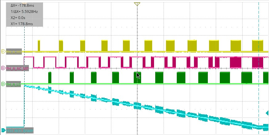
Below is Plot 1 basically using down ramp connected to RED and FED ports on ePWM block.

Scope limited to 4 channels:

         Yellow Trace = HS Gate Signal; PH_A

     Magenta Trace = AC MP Gate Signal; PH_A

          Green Trace = LS Gate Signal; PH_A

             Light Blue = RED_FED Dwn Counter ramp  (count starts around 1800 stops at desired value of                                     12)

image.png


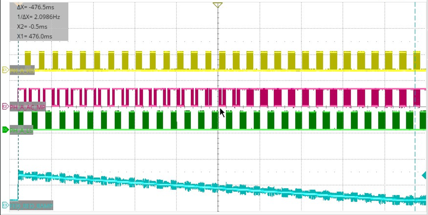
Below is similar Plot but using a different RED_FED Start value, approx 700.  Same stop value of 12.

Using a much higher delay in down counter to stretch out the pwms

image.png

Comments and Questions:

  1.  Do these ePWMs represent what is being inferred in the TIDA-01606 for Soft Start?
    1. a. Would this interpretation seem valid if all 3 phases were soft started this same way?
      1. All ePWMs are using the same Deadband RED FED down ramp signal with;
        1. AHC
        2. Using ePWMA for RED FED
        3. Reload for DBRED and DBFED is "immediate without shadow."
  2. If this interpretation is not correct looking help would be appreciated.

Best,

Colin


  • Hi Colin,

    Unfortunately, we do not have the soft start waveforms captured in the test report. The expected waveform would be the duty cycle will be slowly increasing to the final nominal values from very low values. The code for this is readily available in the DPSDK and can be checked out on a control card without actual power hardware. This should enable you to compare with the Matlab results.

    Thanks, Pawan

  • Hello Pawan,

    Thanks for getting back to me and for the suggestion.

    Regarding Digital Power SDK code reference.  Just to confirm, are you referring to the "tinv_F28379D" project?

    If above is going in the right direction; I would need to run "lab 6" this is where the soft start scheme is introduced.

    To run this lab and generate ePWMs I would need to generate the following signals, correct?

  • Continuation of first reply; accidently posted before I was done.

    Would need to generate the following signals.

    TINV_vGridRms_A_sensed_Volts

    TINV_iGridRms_A_sensed_Amps

    TINV_vGridRms_B_sensed_Volts

    TINV_iGridRms_B_sensed_Amps

    TINV_vGridRms_C_sensed_Volts

    TINV_iGridRms_C_sensed_Amps

    The current signals would be SD modulation signals; so would need a SD Modulators

    The voltage signals would be needed to generate the PLL signal for the transforms.

    Does this sound correct or is there an even easier path?

  • Hi Colin,

    The same code from lab 6 can be copy pasted into lab 1. In this case you can run open loop without sensing any signals. Use the below code.

    TINV_HAL_updatePWMDeadBand(TINV_deadBand);

    TINV_deadBandSlewUpdate++;

    if(TINV_deadBand > TINV_deadBandMin && TINV_deadBandSlewUpdate == 1)
    {
    TINV_deadBand = TINV_deadBand - 1;
    TINV_deadBandSlewUpdate = 0;
    }

    Initialize TINV_deadBand to maximum value.

  • Hello Pawan,

    We did your instruction of pasting Lab_6 deadBand code into Lab_1 of TIDA-01606 Design Guide.

    Below is screenshot of the result.

    Yellow is High Side FET; Green is one of the mid-point FETs associated with HS FET; Blue is Low Side FET

    This screenshot does resemble what we saw regarding previous screenshots in email trail above.  Ours is a bit more drawn out. 

    So, would we only need like a cycle or 2 of soft start to null the inrush current spike sufficiently?

    Thank you much for your help, it is much appreciated.

    Best,

    Colin

  • Saw screenshot in post above was not showing so posted this one.

  • Would recommend trying this out in simulation or hardware at lower voltages. The slew update can be programmable. In code we can either select the deadband step or the rate at which this is decremented. Some amount of iterative testing would be needed.

  • Will do.  Am hoping to try out at lower voltage on hardware today 12_15_25.  Will update with a screenshot, if all goes well.

  • Sure, let us know if you have any further queries on the software.

  • Hello Pawan,

    Yesterday we tested at low voltage and all went well.

    Today we will ramp up to application level voltages.

    Don't have any good screenshots to share yet.

    Thanks again for your help!

    Best,

    Colin

  • Hi Colin,

    I will close this thread. Feel free to open again.

    Best regards, Pawan