This thread has been locked.

If you have a related question, please click the "Ask a related question" button in the top right corner. The newly created question will be automatically linked to this question.

how to configure AIO

Other Parts Discussed in Thread: TMS320F28035, CONTROLSUITE

Hi,

According to table 59 from Document 'TMS320F2803x Piccolo System Control and Interrupts' (pg84), as shown below,

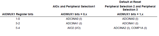
I am supposed to be able to configure pin#16 (TMS320F28035) as AIO2.

But, after I enabled AIO2 by

       EALLOW;
       GpioCtrlRegs.AIOMUX1.bit.AIO4 = 1;  
       EDIS;

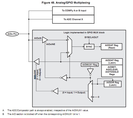
I could still read data through ADC  (i.e. AdcResult.ADCRESULT1 )

I am kinda of confused. Does anyone know why this is happening?

Thank you,

Frank

  • Enabling the AIO pin does not disable the path from the pin to the ADC.  It does let the AIO pin logic access the pin though (so you can read the digital value on the pin or output a digital value).  You can see this in Fig. 48 in the Piccolo System Control Guide:

  • Hi Devin,

    You said, "so you can read the digital value on the pin or output a digital value"

    My understanding on digital value is that it's either 1 or 0, (high or low). So, I think the possible way to use AIO is to use its status register, is that correct?

    Another question, I know the input range is supposed to be 0V to 3.3 V, but how does the AIO decide the input is high or low?

    Thank you,

    Frank

  • The AIO is essentially a GPIO that is muxed with an ADC pin.  There are some differences, for example the AIO does not have a pull up resistor or configurable qualification.  

    The levels that the AIO will recognize on the input are high and low are specified in the datasheet as VIL and VIH:


  • Thank you, Devin.

    Frank

  • Hi, the use of the AOI pin can extend the IO pins for Piccolo applications.

    I use controlsuite V210 for the 28027, but there are no funtions to work with the AIO pins in the library package.

    The GPIO_xxx   funtions only seem to work for the GPIO only.

    It would be a good improvement to add the AIO to the library.

  • Thanks for the feedback.  I'll add this as a feature request.

  • Hi all. I cannot understand what is the purpose of the instruction:

           EALLOW;
           GpioCtrlRegs.AIOMUX1.bit.AIO4 = 1;  
           EDIS;

    I understand that the analog signal to pin 14 is the input of both ADCINA4 and COMP2A regardless of the above instruction.

    1) With AIOMUX1 I can read the analog signal as a digital signal? So I get a one for a high enough input?

    2) If i set port direction (using AIODIR) as output and i drive the output high, do i drive both the input of ADCA4 and the input of the comparator2A?

    3) So what is the difference between 

           EALLOW;
           GpioCtrlRegs.AIOMUX1.bit.AIO4 = 1;  
           EDIS;

    and 

           EALLOW;
           GpioCtrlRegs.AIOMUX1.bit.AIO4 = 2;  
           EDIS;


    Thank you,

    Bing