Part Number: TMS320F28P659DK-Q1
Hello,
I am writing to ask for your support regarding the configuration of the EPWM peripheral.
In our application, we use four peripherals that drive the two legs of two H-bridges.
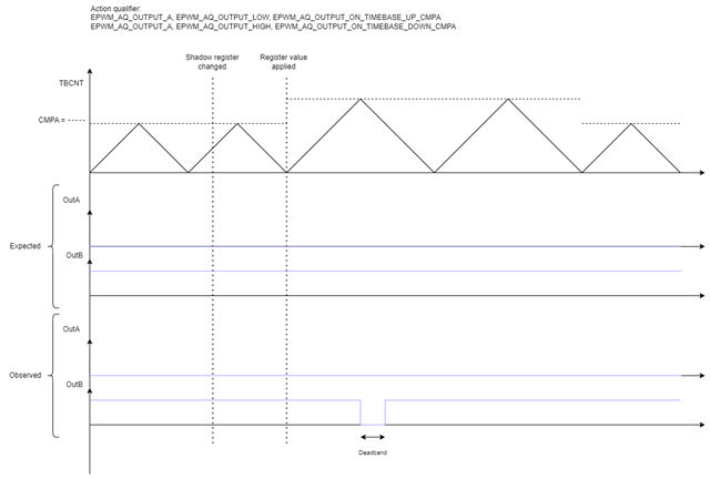
During operation, in the first half-cycle, the MOSFETs of two legs must switch according to a modulating signal, while for the remaining two legs, the drive signal of the high-side MOSFETs must remain low and the drive signal of the low-side MOSFETs must remain high. In the second half-cycle, the behavior must be reversed. In addition to this, we also need to vary the PWM period.
In implementing this behavior, we have seen that, randomly, pulses equal in duration to the deadband are present on the signals driving the low sides (see attached screen).
This behavior only occurs if we also vary the PWM period.
To ensure that the signal is always high on the low side and always low on the high side, during the half-cycle we set the comparator to the same value as the period.
Attached you will also find the firmware, based on one of your examples, which we used to reproduce this behavior.
The PWM peripheral has been configured as follows:
EPWM_setClockPrescaler(myEPWM1_BASE, EPWM_CLOCK_DIVIDER_1, EPWM_HSCLOCK_DIVIDER_1);
EPWM_setTimeBasePeriod(myEPWM1_BASE, 500);
EPWM_setTimeBaseCounter(myEPWM1_BASE, 0);
EPWM_setTimeBaseCounterMode(myEPWM1_BASE, EPWM_COUNTER_MODE_UP_DOWN);
EPWM_disablePhaseShiftLoad(myEPWM1_BASE);
EPWM_setPhaseShift(myEPWM1_BASE, 0);
EPWM_setCounterCompareValue(myEPWM1_BASE, EPWM_COUNTER_COMPARE_A, 250);
EPWM_setCounterCompareShadowLoadMode(myEPWM1_BASE, EPWM_COUNTER_COMPARE_A, EPWM_COMP_LOAD_ON_CNTR_ZERO);
EPWM_setCounterCompareValue(myEPWM1_BASE, EPWM_COUNTER_COMPARE_B, 0);
EPWM_setCounterCompareShadowLoadMode(myEPWM1_BASE, EPWM_COUNTER_COMPARE_B, EPWM_COMP_LOAD_ON_CNTR_ZERO);
EPWM_setActionQualifierAction(myEPWM1_BASE, EPWM_AQ_OUTPUT_A, EPWM_AQ_OUTPUT_LOW, EPWM_AQ_OUTPUT_ON_TIMEBASE_UP_CMPA);
EPWM_setActionQualifierAction(myEPWM1_BASE, EPWM_AQ_OUTPUT_A, EPWM_AQ_OUTPUT_HIGH, EPWM_AQ_OUTPUT_ON_TIMEBASE_DOWN_CMPA);
EPWM_setDeadBandDelayPolarity(myEPWM1_BASE, EPWM_DB_FED, EPWM_DB_POLARITY_ACTIVE_LOW);
EPWM_setDeadBandDelayMode(myEPWM1_BASE, EPWM_DB_RED, true);
EPWM_setRisingEdgeDelayCountShadowLoadMode(myEPWM1_BASE, EPWM_RED_LOAD_ON_CNTR_ZERO);
EPWM_setRisingEdgeDelayCount(myEPWM1_BASE, 20);
EPWM_setDeadBandDelayMode(myEPWM1_BASE, EPWM_DB_FED, true);
EPWM_setFallingEdgeDelayCountShadowLoadMode(myEPWM1_BASE, EPWM_FED_LOAD_ON_CNTR_ZERO);
EPWM_setFallingEdgeDelayCount(myEPWM1_BASE, 20);
EPWM_enableInterrupt(myEPWM1_BASE);
EPWM_setInterruptSource(myEPWM1_BASE, EPWM_INT_TBCTR_ZERO);
EPWM_setInterruptEventCount(myEPWM1_BASE, 3); 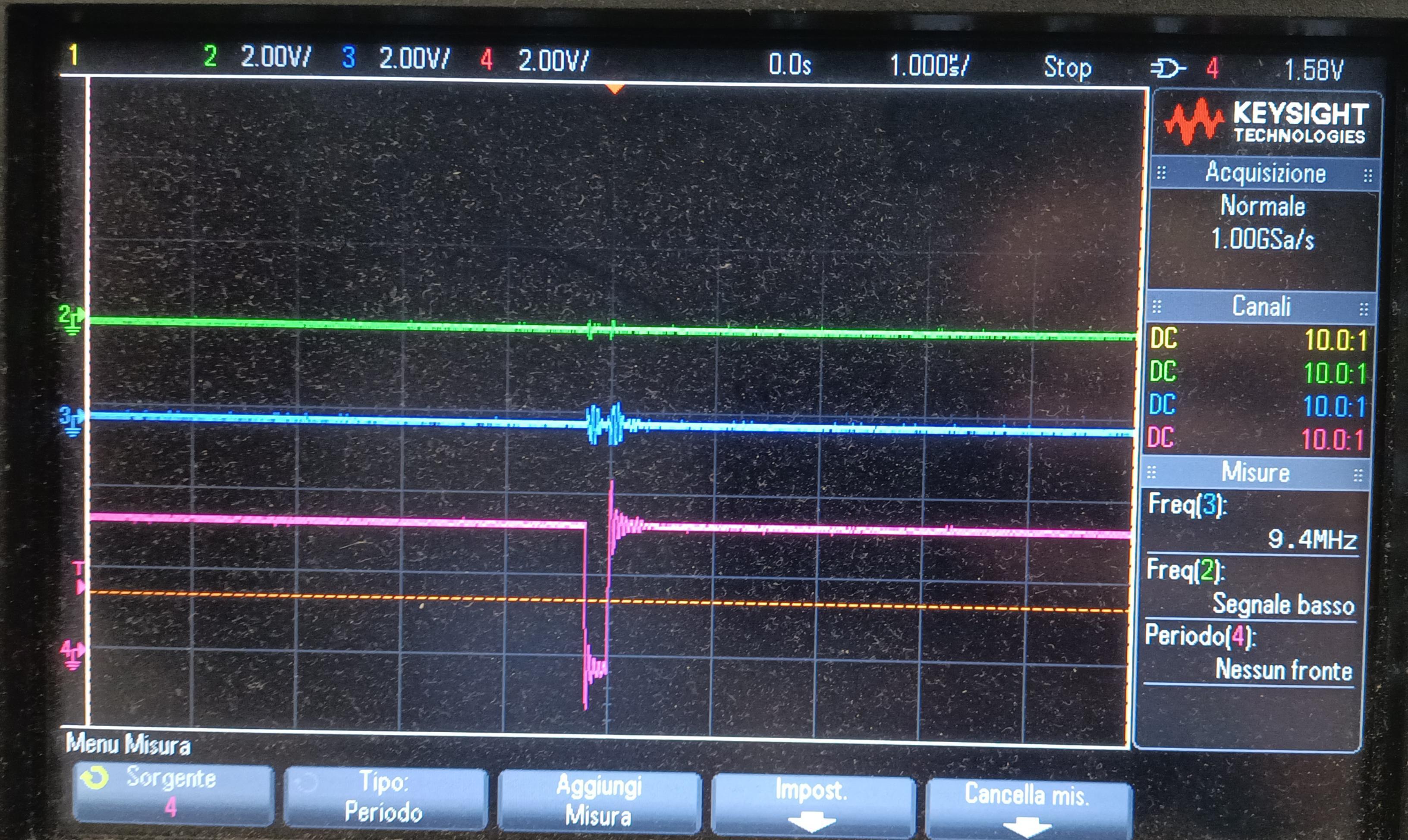
Have you seen similar behavior? Do you have any advice on how to configure the peripheral to avoid it?
Thank you,
Simone