Part Number: TMS320F28379D
Other Parts Discussed in Thread: C2000WARE
Dear Sir/Madam,
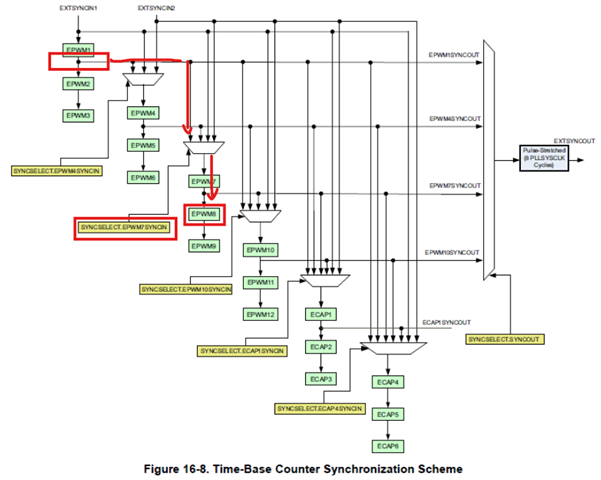
Can you please explain in below code how synchronisation is achieved? Because I want to change the sequence of PWMs to be synchronised.
What is the role of functions
1) SysCtl_setSyncInputConfig
2) EPWM_setSyncOutPulseMode
I am trying to follow C:\ti\c2000\C2000Ware_6_00_01_00\driverlib\f2837xd\examples\cpu1\epwm
epwm_ex3_synchronization example. Below code is also from the same file.
initEPWM(myEPWM1_BASE); //1
//
// Initialize PWM2 with phase shift of 300 TBCLKs
//
initEPWM(myEPWM2_BASE); //2
EPWM_selectPeriodLoadEvent(myEPWM2_BASE, EPWM_SHADOW_LOAD_MODE_SYNC);
EPWM_setPhaseShift(myEPWM2_BASE, 150); //300
EPWM_setTimeBaseCounter(myEPWM2_BASE, 150);
//
// Initialize PWM3 with phase shift of 600 TBCLKs
//
initEPWM(myEPWM3_BASE); //3
EPWM_selectPeriodLoadEvent(myEPWM3_BASE, EPWM_SHADOW_LOAD_MODE_SYNC);
EPWM_setPhaseShift(myEPWM3_BASE, 300); //600
EPWM_setTimeBaseCounter(myEPWM3_BASE, 300);
//
// Initialize PWM4 with phase shift of 900 TBCLKs
//
initEPWM(myEPWM4_BASE); //4
EPWM_selectPeriodLoadEvent(myEPWM4_BASE, EPWM_SHADOW_LOAD_MODE_SYNC);
EPWM_setPhaseShift(myEPWM4_BASE, 450);
EPWM_setTimeBaseCounter(myEPWM4_BASE, 450);
//
// ePWM1 SYNCO is generated on CTR=0
//
EPWM_setSyncOutPulseMode(EPWM1_BASE, EPWM_SYNC_OUT_PULSE_ON_COUNTER_ZERO);
//
// ePWM2 uses the ePWM 1 SYNCO as its SYNCIN.
// ePWM2 SYNCO is generated from its SYNCIN, which is ePWM1 SYNCO
//
EPWM_setSyncOutPulseMode(myEPWM2_BASE, EPWM_SYNC_OUT_PULSE_ON_EPWMxSYNCIN);
//
// ePWM4 uses the ePWM 1 SYNCO as its SYNCIN.
//
SysCtl_setSyncInputConfig(SYSCTL_SYNC_IN_EPWM4, SYSCTL_SYNC_IN_SRC_EPWM1SYNCOUT);
//
// Enable all phase shifts.
//
EPWM_enablePhaseShiftLoad(myEPWM2_BASE);
EPWM_enablePhaseShiftLoad(myEPWM3_BASE);
EPWM_enablePhaseShiftLoad(myEPWM4_BASE);
//
// Enable sync and clock to PWM
//
SysCtl_enablePeripheral(SYSCTL_PERIPH_CLK_TBCLKSYNC);
Thanks and Regards,
Prashant Gugle