


Other Parts Discussed in Thread: CONTROLSUITE
Hello, Its been a wile since I started using Concerto and there might be changes, but i managed to make/generate code on the matlab for the Concerto. Sorry for my "not so fluent" english.
This ‘how to’ is not a step-by-step tutorial and requires that the reader has already installed Matlab/Simulink®, Code Composer Studio® (CCS) and ControlSuite (CS) (at least version 2.6 must be installed). The reader must be familiar with CCS, IQMath® and how to program a microcontroller, in this case the F28M35 Concerto series, a dual core Stellaris/Delfino (LINK). I will no explain how to configure GPIOs or use PWMs, etc...
Before we start you need to prepare your simulink model accordingly and know that:
- The Concerto “Control” side is a Delfino, but if you try and program its ADCs as you would do in a normal Delfino you will notice that its different, the ADC in the Concerto is of type 3 and not of type 2 as in regular Delfino. (see section 3.5 of LINK and chapter 6 of LINK)
- Just a small warning for the readers who are starting to use this link between matlab and CCS: Be aware of IQMath constants, depending on its type/number, their value might saturate.
- After you have your model working/compiling without errors, execute the command xmakefilesetup on matlab console and change the options according to this LINK. Afterwards, press Ctrl+E in your model to access the model configuration window, and in the IDE/Tool Chain selection choose: makefile generation only, see Fig. 1
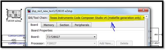
Fig. 1 Select makefile generation only
Compile the code using Ctrl+B in your Simulink model. During the process, matlab will generate, in the same folder as the model, a folder with the same name as the model. See Fig 2 for an example were the simulink model name is “dsp_rect_new_test1”.
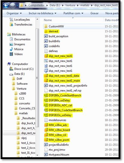
Fig. 2 Files in the matlab generated folder
The files in yellow in Fig. 2 are the ones to be copied to a new project in CCS v4. These files contain the model and some configuration code that would be enough to program the Delfino. Please read the information in chapter 2 of the file in (CS folder) \ device_support \ f28m35x \ v??? \ doc \ F28M35x-FRM-EX-UG.pdf to help you create a new project in CCS v4. Please skip the part for creating a main.c source code. The main() function is already defined in your name_of_model_main.c file.
After the project is created according to the previous pdf file, you need to add the files created by Matlab to the project (adding them, not linking). To add files right click your project with in CCS and select “Add Files…”. Do this for rtwtypes.h present in the generated folder and every file in yellow according to Fig. 2. (leave the folder derived). For CCS to compile properly you will have to link (Link Files… in right button menu) the file c2000_main.h present in you matlab installation folder: ... \ MATLAB \ R20XXx \ toolbox \ idelink \ extensions \ ticcs \ inc \ .
So far so good, now you need to change the Included files in the several source files generated by Matlab (that are for the Delfino in the format DSP280x…h!) Luckily, as they are “the same” microcontrollers the names are almost equal and you just have to change from DSP280x format to F28M35x format in most of the cases. For that check these folders:
C:\TI\controlSUITE\device_support\f28m35x\v100\F28M35x_common\source
C:\TI\controlSUITE\device_support\f28m35x\v100\F28M35x_common\include
C:\TI\controlSUITE\device_support\f28m35x\v100\F28M35x_headers\include
C:\TI\controlSUITE\device_support\f28m35x\v100\F28M35x_headers\source
To help identifying the F28M35x.XXX.h/c files needed to add/link to the project you can make a list of the .obj files generated by matlab compiler, present in the “derived” folder identified in yellow in Fig. 2. In Fig 3 you can see an example of all the files added and linked for my project where I use the ADC, PWM and SPI peripherals.
Considering that the Delfino/control part of the Concerto doesn’t need the same initial setup as the normal Delfino, and that we changed the include files it is necessary to configure the appropriate ports and system configuration in the ARM/Master part of the Concerto. This is outside the scope of this small “tutorial”, please read the appropriate documentation. If you don’t know what to do and just want to use the Delfino part of the Concerto with matlab generated code, please compile and run “setup_m3” project on your ARM (can be found in …controlSUITE \ device_support \ f28m35x \ version \ F28M35x_examples_Control). This will give the Delfino access to all the peripherals and pins/legs of the Concerto chip (PWM, GPIO, etc)
After this is up to the user to decide which functions to change as they will be different from user to user. I leave a list for common changes:
• init_board() function, in MW_c28xx_board.c should be edited to be compatible with the Concerto, the initial setup where the System and peripherals clocks are defined should be skipped as this is done on the ARM part.
• The function name_of_model_initialize() in the file name_of_model.c can be changed according to the needs of your GPIO. (Remember, the clock associated with GPIO, the pull-up resistances, direction, etc. are configured on the ARM side).
• c2000_main.h is a strange file :) I’ve been trying to figure out what it does but with no luck. This file makes validations on variables that might generate errors as being undeclared. To avoid these errors please comment (Ctrl+Shift+7) the lines that check for RT, MODEL, NUMST e NCSTATES. Or you can define them in your code if you know what they mean. (RT prob. means real time, but it is not used anywhere on the code, at least in my code, so far).
• In my application I had to add to the ADC configuration the following lines to be able to use the ePWM module to start the ADC acquisition:
AnalogSysctrlRegs.TRIG1SEL.all = 5;
Adc1Regs.ADCCTL2.bit.ADCNONOVERLAP = 1;
These commands tell the ADC module to monitor ePWM1 to start an acquisition (read the Concerto Techincal Manual for more configuration possibilities)
• With these changes your code probably compiles without errors and if lucky with no warnings (If you find errors stating that you have undeclared functions, please look for them in the .c files and make a .h files with the same function names and declare them as they are in the .c files - make a header file for the source file generated by matlab). I had this problem with the initialization of the ADC, the function was declared in the c. file of MW_c28xx_adc.c but it wasn’t recognized by the compiler until I added a MWc28xx_adc.h and included it on name_of_model.c.
Contents of MWc28xx_adc.h:
#ifndef MW_C28XX_ADC_H_
#define MW_C28XX_ADC_H_
void InitAdc(void);
void config_ADC_SOC0(void);
void config_ADC_SOC1(void);
void config_ADC_SOC2(void);
void config_ADC_SOC3(void);
void config_ADC_SOC4(void);
void config_ADC_SOC5(void);
#endif /*MW_C28XX_ADC_H_*/
To be able to use the PWM I had to do the same with the GPIO configuration functions, made a file called MW_c28xx_pwm.h with the following contents:
#ifndef MW_C28XX_PWM_H_
#define MW_C28XX_PWM_H_
void config_ePWM_GPIO (void);
#endif /*MW_C28XX_PWM_H_*/
In Fig 3 there is a list of all the files I needed to compile (without errors and warnings) a small 3 phase rectifier, which means, 5 ADC channels, 3 PWMs (A and B = 6 signals total).

Fig. 3 List/example of the files needed for CCS
Hoping this will be helpful,
Rui Ventura


