


Part Number: TMS320F28379D
Hello,
I'm trying to drive an external DAC using an EPWM triggered DMA to write from a 24-point sine wave table to my SPI transmit buffer. I've mapped my EPWM to a GPIO to monitor its output. I'm seeing the SPI peripheral transmit 16 clock pulses and drive chip select low on the rising edge of each EPWM pulse, however, no data is being transmitted over MOSI (see picture, first few SPI writes are manual).
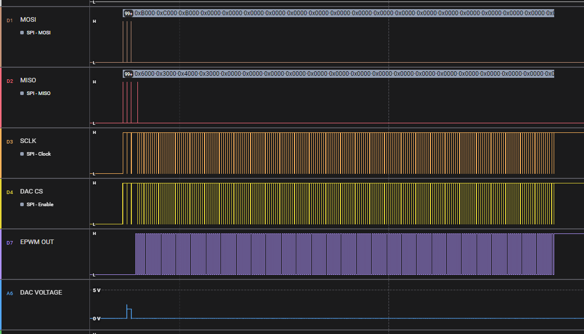
This would indicate to me that the DMA is being triggered by my EPWM, but for some reason the data is not transferring correctly between the DMA and SPI. I'm also confused because I'm monitoring some of the DMA flags in the debug, and I see the following flags remain the same during runtime:
- DMA_getTransferStatusFlag = DMA_getRunStatusFlag = 1
- DMA_getTriggerFlagStatus = 0
So I'm not sure if the DMA is actually being triggered or not.
I'm wondering if somebody can take a look at my DMA config and point out if there's something obvious I'm missing. I suspect my issue is very similar to what's described in this thread but unfortunately this user doesn't elaborate what changes they made (Sinewave generation using EPWM, DMA, and DAC). Here's my config:
extern uint16_t waveformDATA[24];
#define mySPI0_TX_DMA_ADDRESS (SPIA_BASE + SPI_O_TXBUF)
void DMA_init(){
    DMA_initController();
	myDMA0_init();
}

void myDMA0_init(){
    DMA_setEmulationMode(DMA_EMULATION_STOP);
    DMA_configAddresses(myDMA0_BASE, (const void *)mySPI0_TX_DMA_ADDRESS, (const void *)waveformDATA);
    DMA_configBurst(myDMA0_BASE, 1U, 1, 0);
    DMA_configTransfer(myDMA0_BASE, 24U, 1, 0);
    DMA_configWrap(myDMA0_BASE, 24U, -24, 65535U, 0);
    DMA_configMode(myDMA0_BASE, DMA_TRIGGER_EPWM6SOCA, DMA_CFG_ONESHOT_DISABLE | DMA_CFG_CONTINUOUS_ENABLE | DMA_CFG_SIZE_16BIT);
    //DMA_stopChannel(myDMA0_BASE);
	DMA_enableInterrupt(myDMA0_BASE);
    DMA_setInterruptMode(myDMA0_BASE, DMA_INT_AT_END);
	//DMA_clearTriggerFlag(myDMA0_BASE);
	DMA_enableTrigger(myDMA0_BASE);
}
Best,
Malcolm


