Part Number: TMDSDOCK28379D
Other Parts Discussed in Thread: TMDSCNCD28379D,
We are currently developing a custom base board for the controlCARD TMDSCNCD28379D.
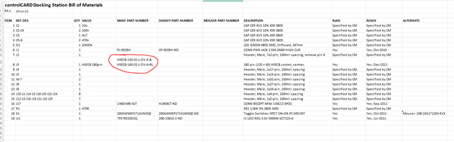
In the TMDSDOCK28379D docking station, the following HSEC connectors are used to interface with the controlCARD:
-
HSEC8-160-01-L-DV-A-BL for the 120-pin connection
-
HSEC8-130-01-L-DV-A for the 60-pin connection
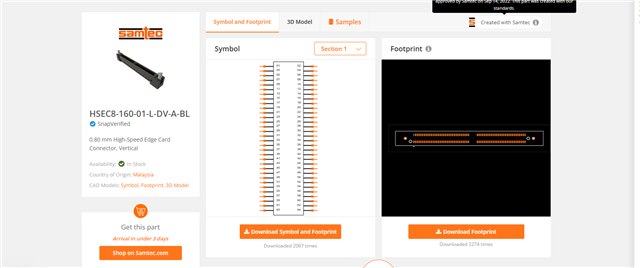
Upon reviewing the footprint of the HSEC8-160-01-L-DV-A-BL connector, we observed that the pins are physically divided into two sections:
-
Pins 1 to 64 as one part
-
Pins 65 to 120 as another part
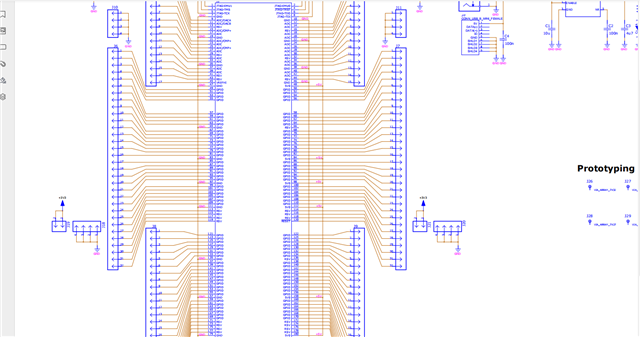
However, when pairing with the controlCARD, the connection is possible only such that Pin 1 of the controlCARD mates with Pin 120 of the HSEC8-160-01-L-DV-A-BL connector on the docking station. This reverse pin alignment is not clearly mentioned or explained in the schematic or documentation.
We kindly request your clarification on the following points:
-
Is this reverse pin mapping (controlCARD Pin 1 ↔ HSEC Pin 120) intentional by design?
-
Is there any official documentation or application note that explains this pin numbering and mating orientation in detail?
-
Are there any specific guidelines we should follow while designing a custom base board using these HSEC connectors?