This thread has been locked.

If you have a related question, please click the "Ask a related question" button in the top right corner. The newly created question will be automatically linked to this question.

TMS320F28377D: Bissc non-stop clock issue

Part Number: TMS320F28377D
Other Parts Discussed in Thread: C2000WARE

Hi Experts,

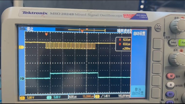
My customer is having bissc issue where the encoder clock would last longer than expected and only stop at the next cycle. Below is an example waveform

3dbf49817e4dc7cbd2cd56389105b88a.jpeg

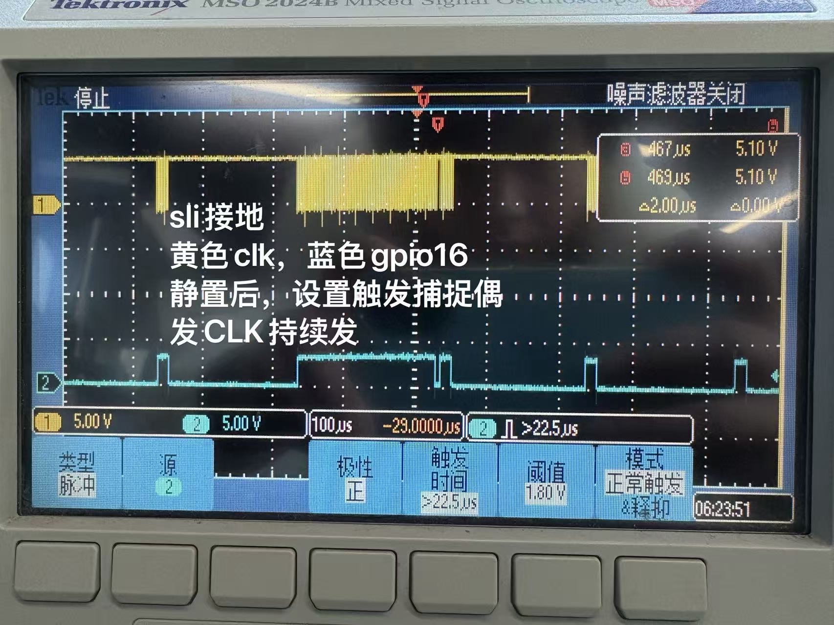
The yellow is the encoder clock and the blue is a GPIO connected output of the primary state machine FSM1 

image.png

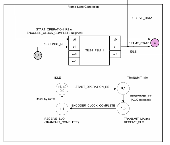
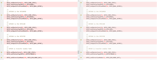
The GPIO is connected to the outlut5 of the CLB. Since the F2879d biss-c CLB project is not open source, we can only take reference from the F28P65 project in the motor control SDK, where the outlut5 is set as the output of FSM1 S0.

image.png

However, the below zoom-in picture shows that the blue turns high after several cycles of encoder clocks, this is more similar to the behavior of FSM1.S1 instead of FSM1.S0, I am confused.

Could you please help confirming if the outlut5 and outlut6 is the FSM S0 and FSM S1 respectively on F28379? This will determined which state the state machine is stuck.


In the meantime, this issue only happens by chance, on some boards. ABA test shows that the issue follows the DSP.

What might the cause of this issue?

Regards,

Hang

  • Hi Hang,

    The OUTLUT you connect S1 or S0 of FSM1 shouldn't affect anything as long as you have the correct connection of said OUTLUT to the next TILE afterwards. I am not that familiar with Biss-c or this specific reference project, however I have just looped in an expert for comment. 

    Kind regards,

    AJ Favela 

  • Hi Hang, I need a day to look into this. Thank you.

    Lori

  • My apologies, I need another day to look into this. 

  • Hi Lori,

    As discussed, customer tested the example project in the MSS with minimum modification to adapt the pinout of the custom board, and they are about to reproduce the issue with the example.

    Below is the changes of the example:


    In the meantime, they find that the issue is related to the status of the CPU2. If CPU2 is not booted, the issue will not occur. If CPU2 is booted, the issue will occur.

    The code running in CPU2 is just the IPC example.

    C2000Ware_6_00_00_00\device_support\f2837xd\examples\dual\cpu01_to_cpu02_ipcdrivers\cpu02

    They also tried running while(1) in CPU2, and the issue will still occur, with a slight difference in time it takes from power-on to the occurrence of the issue.

    Below are two videos of the oscilloscope.

    Both CPU1 and CPU2 are booted, the issue will occur:

    Not booting CPU2, the issue will not occur:

    In the two video, yellow is the encoder clock and green is the encoder response.

    Is there any suggestion how to debug next?

  • This is strange. I don't see how the state of CPU2 could influence the number of SPI clocks sent by the CLB. I need some time to think about this.

  • Hang, Does this happen on a launchPad + BOOSTXL_POSMGR setup as well? Can we rule out a hardware issue like power supply, any resets occuring?