This thread has been locked.

If you have a related question, please click the "Ask a related question" button in the top right corner. The newly created question will be automatically linked to this question.

LAUNCHXL-F28P55X: [Bug Report] MCAN Interrupt is not triggered under debug session F28P55X

Part Number: LAUNCHXL-F28P55X
Other Parts Discussed in Thread: C2000WARE, SYSCONFIG

Hi, 

I am developing the MCAN protocol with the C2000Ware(6.00.00.00) SDK with the F28P55X dev-kit.

I have noticed the configured interrupt line is not entered during debug (Tx and Rx FIFO event) and I can only varify if the interrupt is triggered by toggling a GPIO pin.

Could you please look into it?

Thanks,

Siu 

  • Hi Siu,

    Have you enabled the interrupt properly?

    1. Enable MCAN interrupt in PIE 

    2. Register MCAN interrupt to PIE table (copy MCAN ISR address to PIE interrupt vector table)

    3. Enable Globle interrupt

    4. Enable MCAN interrupt in MCAN module: MCAN_IE: 

    5. Select and enable the MCAN interrupt line: 0 or 1

  • Hi QJ,

    Thanks for your reply.

    I am using syscfg to config the MCAN module in the project.

    The issue I am having is, the programme does not stop at the breakpoint in the registered interrupt INT_MCAN0_ISR in debugging session but I can see a gpio is toggling inside the function when running the application.

    I have also notice the CAN transmission doesn't work when running debugging session; however, once I power cycle the f28p55x dev-kit I can see the CAN traffic on bus master without debugging.

    1. Enable MCAN interrupt in PIE 

    - Yes

    2. Register MCAN interrupt to PIE table (copy MCAN ISR address to PIE interrupt vector table)

    - Yes

    3. Enable Globle interrupt

    - Yes

    4. Enable MCAN interrupt in MCAN module: MCAN_IE: 

    - Yes

    5. Select and enable the MCAN interrupt line: 0 or 1

    - Yes Line 0 selected

    Please find below generated board.c file.

    #include "board.h"
    
    void Board_init()
    {
    	EALLOW;
    
    	PinMux_init();
    	SYSCTL_init();
    	MCAN_SYSCFG_init();
    	INTERRUPT_init();
    
    	EDIS;
    }
    
    //*****************************************************************************
    //
    // PINMUX Configurations
    //
    //*****************************************************************************
    void PinMux_init()
    {
    	//
    	// PinMux for modules assigned to CPU1
    	//
    
    	//
    	// MCANA -> MCAN0 Pinmux
    	//
    	GPIO_setPinConfig(MCAN0_MCANRX_PIN_CONFIG);
    	GPIO_setPadConfig(MCAN0_MCANRX_GPIO, GPIO_PIN_TYPE_STD);
    	GPIO_setQualificationMode(MCAN0_MCANRX_GPIO, GPIO_QUAL_ASYNC);
    
    	GPIO_setPinConfig(MCAN0_MCANTX_PIN_CONFIG);
    	GPIO_setPadConfig(MCAN0_MCANTX_GPIO, GPIO_PIN_TYPE_STD);
    	GPIO_setQualificationMode(MCAN0_MCANTX_GPIO, GPIO_QUAL_ASYNC);
    }
    
    //*****************************************************************************
    //
    // INTERRUPT Configurations
    //
    //*****************************************************************************
    void INTERRUPT_init(){
    	// Interrupt Settings for INT_MCAN0_0
    	// ISR need to be defined for the registered interrupts
    	Interrupt_register(INT_MCAN0_0, &INT_MCAN0_ISR);
    	Interrupt_enable(INT_MCAN0_0);
    }
    //*****************************************************************************
    //
    // MCAN Configurations
    //
    //*****************************************************************************
    void MCAN_SYSCFG_init(){
        MCAN0_init();
    }
    
    void MCAN0_init(){
        MCAN_RevisionId revid_MCAN0;
        MCAN_InitParams initParams_MCAN0;
        MCAN_MsgRAMConfigParams    msgRAMConfigParams_MCAN0;
        MCAN_BitTimingParams       bitTimes_MCAN0;
        //
        // Initialize MCAN Init parameters.
        //
        initParams_MCAN0.fdMode            = false;
        initParams_MCAN0.brsEnable         = false;
        initParams_MCAN0.txpEnable         = false;
        initParams_MCAN0.efbi              = false;
        initParams_MCAN0.pxhddisable       = false;
        initParams_MCAN0.darEnable         = false;
        initParams_MCAN0.wkupReqEnable     = false;
        initParams_MCAN0.autoWkupEnable    = false;
        initParams_MCAN0.emulationEnable   = false;
        initParams_MCAN0.tdcEnable         = false;
        initParams_MCAN0.wdcPreload        = 255;
        //
        // Transmitter Delay Compensation parameters.
        //
        initParams_MCAN0.tdcConfig.tdcf    = 10;
        initParams_MCAN0.tdcConfig.tdco    = 6;
        //
        // Initialize Message RAM Sections Configuration Parameters.
        //
        msgRAMConfigParams_MCAN0.flssa                = MCAN0_MCAN_STD_ID_FILT_START_ADDR;
        //
        // Standard ID Filter List Start Address.
        //
        msgRAMConfigParams_MCAN0.lss                  = MCAN0_MCAN_STD_ID_FILTER_NUM;
        //
        // List Size: Standard ID.
        //
        msgRAMConfigParams_MCAN0.flesa                = MCAN0_MCAN_EXT_ID_FILT_START_ADDR;
        //
        // Extended ID Filter List Start Address.
        //
        msgRAMConfigParams_MCAN0.lse                  = MCAN0_MCAN_EXT_ID_FILTER_NUM;
        //
        // List Size: Extended ID.
        //
        msgRAMConfigParams_MCAN0.txStartAddr          = MCAN0_MCAN_TX_BUFF_START_ADDR;
        //
        // Tx Buffers Start Address.
        //
        msgRAMConfigParams_MCAN0.txBufNum             = MCAN0_MCAN_TX_BUFF_SIZE;
        //
        // Number of Dedicated Transmit Buffers.
        //
        msgRAMConfigParams_MCAN0.txFIFOSize           = 32;
        msgRAMConfigParams_MCAN0.txBufMode            = 0;
        msgRAMConfigParams_MCAN0.txBufElemSize        = 0;
        //
        // Tx Buffer Element Size.
        //
        msgRAMConfigParams_MCAN0.txEventFIFOStartAddr = MCAN0_MCAN_TX_EVENT_START_ADDR;
        //
        // Tx Event FIFO Start Address.
        //
        msgRAMConfigParams_MCAN0.txEventFIFOSize      = MCAN0_MCAN_TX_EVENT_SIZE;
        //
        // Event FIFO Size.
        //
        msgRAMConfigParams_MCAN0.txEventFIFOWaterMark = 0;
        //
        // Level for Tx Event FIFO watermark interrupt.
        //
        msgRAMConfigParams_MCAN0.rxFIFO0startAddr     = MCAN0_MCAN_FIFO_0_START_ADDR;
        //
        // Rx FIFO0 Start Address.
        //
        msgRAMConfigParams_MCAN0.rxFIFO0size          = MCAN0_MCAN_FIFO_0_NUM;
        //
        // Number of Rx FIFO elements.
        //
        msgRAMConfigParams_MCAN0.rxFIFO0waterMark     = 0; // Rx FIFO0 Watermark.
        msgRAMConfigParams_MCAN0.rxFIFO0OpMode        = 0;
        msgRAMConfigParams_MCAN0.rxFIFO1startAddr     = MCAN0_MCAN_FIFO_1_START_ADDR;
        //
        // Rx FIFO1 Start Address.
        //
        msgRAMConfigParams_MCAN0.rxFIFO1size          = MCAN0_MCAN_FIFO_1_NUM;
        //
        // Number of Rx FIFO elements.
        //
        msgRAMConfigParams_MCAN0.rxFIFO1waterMark     = 0; // Level for Rx FIFO 1
                                                      // watermark interrupt.
        msgRAMConfigParams_MCAN0.rxFIFO1OpMode        = 0; // FIFO blocking mode.
        msgRAMConfigParams_MCAN0.rxBufStartAddr       = MCAN0_MCAN_RX_BUFF_START_ADDR;
        //
        // Rx Buffer Start Address.
        //
        msgRAMConfigParams_MCAN0.rxBufElemSize        = 0;
        //
        // Rx Buffer Element Size.
        //
        msgRAMConfigParams_MCAN0.rxFIFO0ElemSize      = 0;
        //
        // Rx FIFO0 Element Size.
        //
        msgRAMConfigParams_MCAN0.rxFIFO1ElemSize      = 0;
        //
        // Rx FIFO1 Element Size.
        //
        //
        // Initialize bit timings.
        //
        bitTimes_MCAN0.nomRatePrescalar   = 5; // Nominal Baud Rate Pre-scaler.
        bitTimes_MCAN0.nomTimeSeg1        = 4; // Nominal Time segment before sample point.
        bitTimes_MCAN0.nomTimeSeg2        = 3; // Nominal Time segment after sample point.
        bitTimes_MCAN0.nomSynchJumpWidth  = 4; // Nominal (Re)Synchronization Jump Width Range.
        bitTimes_MCAN0.dataRatePrescalar  = 3; // Data Baud Rate Pre-scaler.
        bitTimes_MCAN0.dataTimeSeg1       = 4; // Data Time segment before sample point.
        bitTimes_MCAN0.dataTimeSeg2       = 3; // Data Time segment after sample point.
        bitTimes_MCAN0.dataSynchJumpWidth = 3; // Data (Re)Synchronization Jump Width.
        //
        // Get MCANSS Revision ID.
        //
        MCAN_getRevisionId(MCAN0_BASE, &revid_MCAN0);
        //
        // Wait for Memory initialization to be completed.
        //
        while(0 == MCAN_isMemInitDone(MCAN0_BASE));
        //
        // Put MCAN in SW initialization mode.
        //
        MCAN_setOpMode(MCAN0_BASE, MCAN_OPERATION_MODE_SW_INIT);
        //
        // Wait till MCAN is not initialized.
        //
        while (MCAN_OPERATION_MODE_SW_INIT != MCAN_getOpMode(MCAN0_BASE));
        //
        // Initialize MCAN module.
        //
        MCAN_init(MCAN0_BASE, &initParams_MCAN0);
        //
        // Configure Bit timings.
        //
        MCAN_setBitTime(MCAN0_BASE, &bitTimes_MCAN0);
        //
        // Configure Message RAM Sections
        //
        MCAN_msgRAMConfig(MCAN0_BASE, &msgRAMConfigParams_MCAN0);
        //
        // Internal loopback mode
        //
        MCAN_lpbkModeEnable(MCAN0_BASE, MCAN_LPBK_MODE_EXTERNAL, false);
        //
        // Take MCAN out of the SW initialization mode
        //
        MCAN_setOpMode(MCAN0_BASE, MCAN_OPERATION_MODE_NORMAL);
        while (MCAN_OPERATION_MODE_NORMAL != MCAN_getOpMode(MCAN0_BASE));
        //
        // Enable MCAN Interrupts
        //
        MCAN_enableIntr(MCAN0_BASE, MCAN_IR_ELO_MASK|MCAN_IR_EP_MASK|MCAN_IR_RF0N_MASK|MCAN_IR_TEFN_MASK, 1U);
        MCAN_selectIntrLine(MCAN0_BASE, MCAN_IR_ELO_MASK|MCAN_IR_EP_MASK|MCAN_IR_RF0N_MASK|MCAN_IR_TEFN_MASK, MCAN_INTR_LINE_NUM_0);
        MCAN_enableIntrLine(MCAN0_BASE, MCAN_INTR_LINE_NUM_0, 1U);
    }
    
    //*****************************************************************************
    //
    // SYSCTL Configurations
    //
    //*****************************************************************************
    void SYSCTL_init(){
    	//
        // sysctl initialization
    	//
        SysCtl_setStandbyQualificationPeriod(2);
        SysCtl_enableNMIGlobalInterrupt();
        SysCtl_configureType(SYSCTL_USBTYPE, 0, 0);
        SysCtl_configureType(SYSCTL_ECAPTYPE, 0, 0);
        SysCtl_selectErrPinPolarity(0);
    
        SysCtl_enableMCD();
    
        SysCtl_setPeripheralAccessControl(SYSCTL_ACCESS_MCANA, 
            SYSCTL_ACCESS_CPU1, SYSCTL_ACCESS_FULL);
        SysCtl_setPeripheralAccessControl(SYSCTL_ACCESS_MCANA, 
            SYSCTL_ACCESS_CLA1, SYSCTL_ACCESS_FULL);
        SysCtl_setPeripheralAccessControl(SYSCTL_ACCESS_MCANA, 
            SYSCTL_ACCESS_DMA1, SYSCTL_ACCESS_FULL);
        SysCtl_setPeripheralAccessControl(SYSCTL_ACCESS_MCANB, 
            SYSCTL_ACCESS_CPU1, SYSCTL_ACCESS_FULL);
        SysCtl_setPeripheralAccessControl(SYSCTL_ACCESS_MCANB, 
            SYSCTL_ACCESS_CLA1, SYSCTL_ACCESS_FULL);
        SysCtl_setPeripheralAccessControl(SYSCTL_ACCESS_MCANB, 
            SYSCTL_ACCESS_DMA1, SYSCTL_ACCESS_FULL);
    
        SysCtl_enablePeripheral(SYSCTL_PERIPH_CLK_MCANA);
        SysCtl_enablePeripheral(SYSCTL_PERIPH_CLK_MCANB);
    
    }

    Thanks,

    Siu

  • Hi Siu,

    Are you using sysconfig for MCAN and clock configuration? If yes, can you share the sysconfig file?

  • Are you able to receive the MCAN message in polling mode? 

  • Hi QJ,

    Please find attached the syscfg file. I just added .txt extension so I can upload the file.

    /**
     * These arguments were used when this file was generated. They will be automatically applied on subsequent loads
     * via the GUI or CLI. Run CLI with '--help' for additional information on how to override these arguments.
     * @cliArgs --board "/boards/LAUNCHXL_F28P55X" --device "F28P55x" --part "F28P55x_100PZ" --package "100PZ" --context "system" --product "C2000WARE@5.04.00.00"
     * @v2CliArgs --board "/boards/LAUNCHXL_F28P55X" --device "TMS320F28P550SG" --package "100PZ" --variant "TMS320F28P550SG8" --context "system" --product "C2000WARE@5.04.00.00"
     * @versions {"tool":"1.24.0+4110"}
     */
    
    /**
     * Import the modules used in this configuration.
     */
    const led       = scripting.addModule("/driverlib/board_components/led", {}, false);
    const led1      = led.addInstance();
    const led2      = led.addInstance();
    const mcan      = scripting.addModule("/driverlib/mcan.js", {}, false);
    const mcan1     = mcan.addInstance();
    const sysctl    = scripting.addModule("/driverlib/sysctl.js");
    const FREERTOS  = scripting.addModule("/kernel/freertos_tool/FREERTOS", {}, false);
    const FREERTOS1 = FREERTOS.addInstance();
    
    /**
     * Write custom configuration values to the imported modules.
     */
    led1.$hardware = system.deviceData.board.components.LED4;
    led1.$name     = "RUN_LED_0";
    
    led2.$hardware = system.deviceData.board.components.LED5;
    led2.$name     = "RUN_LED_1";
    
    const divider8       = system.clockTree["PLL_REFDIV"];
    divider8.divideValue = 2;
    
    const mux3       = system.clockTree["OSCCLKSRCSEL"];
    mux3.inputSelect = "X1_XTAL";
    
    mcan1.loopbackMode             = false;
    mcan1.brsEnable                = false;
    mcan1.fdMode                   = false;
    mcan1.registerInterruptLine0   = true;
    mcan1.enableInterrupt          = true;
    mcan1.interruptFlags           = ["MCAN_IR_RF0N_MASK"];
    mcan1.interruptLine            = ["MCAN_INTR_LINE_NUM_0"];
    mcan1.interruptLine0Flag       = ["MCAN_IR_RF0N_MASK"];
    mcan1.lss                      = 0;
    mcan1.lse                      = 0;
    mcan1.txFIFOSize               = 32;
    mcan1.txBufElemSize            = "0";
    mcan1.rxFIFO0size              = 32;
    mcan1.rxBufElemSize            = "0";
    mcan1.rxFIFO0ElemSize          = "0";
    mcan1.rxFIFO1ElemSize          = "0";
    mcan1.useCalcStartingAddress   = true;
    mcan1.$name                    = "MCAN0";
    mcan1.nomRatePrescalar         = 5;
    mcan1.nomSynchJumpWidth        = 4;
    mcan1.mcan.$assign             = "MCANA";
    mcan1.mcan.mcan_rxPin.$assign  = "boosterpack1.31";
    mcan1.mcan.mcan_txPin.$assign  = "boosterpack1.32";
    mcan1.mcanInt0.enableInterrupt = true;
    scripting.suppress("Connected to hardware,@@@.+?@@@ is connected to MCANA BP on the LaunchPad F28P55X\\. Consider selecting it in \'use hardware\' above\\. @@@.+?@@@", mcan1.mcan, "mcan_rxPin");
    scripting.suppress("Connected to hardware,@@@.+?@@@ is connected to MCANA BP on the LaunchPad F28P55X\\. Consider selecting it in \'use hardware\' above\\. @@@.+?@@@", mcan1.mcan, "mcan_txPin");
    
    sysctl.enableMCD                          = true;
    sysctl.enableNMIGlobalInterrupt           = true;
    sysctl.enable_SYSCTL_PERIPH_CLK_TBCLKSYNC = true;
    
    FREERTOS1.$name                     = "myFREERTOS0";
    FREERTOS1.USE_MUTEXES               = true;
    FREERTOS1.USE_RECURSIVE_MUTEXES     = true;
    FREERTOS1.USE_COUNTING_SEMAPHORES   = true;
    FREERTOS1.CPU_CLOCK_HZ              = 150000000;
    FREERTOS1.MINIMAL_STACK_SIZE        = 512;
    FREERTOS1.RECORD_STACK_HIGH_ADDRESS = true;
    FREERTOS1.CHECK_FOR_STACK_OVERFLOW  = 2;
    FREERTOS1.USE_TICK_HOOK             = true;
    FREERTOS1.IDLE_SHOULD_YIELD         = true;
    FREERTOS1.tasks.create(1);
    FREERTOS1.tasks[0].$name            = "periodicThread";
    FREERTOS1.tasks[0].taskPointer      = "SWI_periodicTaskThread";
    FREERTOS1.tasks[0].taskPriority     = 10;
    FREERTOS1.tasks[0].taskStackSize    = 2048;
    
    /**
     * Pinmux solution for unlocked pins/peripherals. This ensures that minor changes to the automatic solver in a future
     * version of the tool will not impact the pinmux you originally saw.  These lines can be completely deleted in order to
     * re-solve from scratch.
     */
    led1.gpio.gpioPin.$suggestSolution = "boosterpack2.53";
    led2.gpio.gpioPin.$suggestSolution = "boosterpack1.13";
    

  • Currently I have one CAN Tx message continuously sending a message with can ID 0x123 with a incrementing number.

    and expect a Rx interrupt when can ID 0x321 is received.

    During debugging session, I can not observe the can Tx message in BUS master nor it stops at the break point inside the Rx interrupt function.

    However, once I flash the programme to the f28p55x dev kit without running debug, I can start seeing the Tx message and toggle a gpio pin inside the Rx interrupt.

    Attached the source file I have.

    // Standard includes
    #include <string.h>
    
    // TI C2000/CGT includes
    #include "board.h"
    #include "mcan.h"
    #include "sysctl.h"
    
    void CAN_localInit(void) {
      SysCtl_setMCANClk(SYSCTL_MCANA, SYSCTL_MCANCLK_DIV_5);
    }
    
    uint32_t CAN_readIdField(const uint32_t &id) {
      uint32_t decodedId = 0U;
      if (((id >> 30U) & 0b1U) == 0U) {
        // 11-bit ID, stored in 28:18
        decodedId = (id >> 18U) & 0x7FFU;
      } else {
        // 29-bit ID, stored in 28:0
        decodedId = (id & 0x1FFFFFFFU);
      }
      return decodedId;
    }
    
    uint32_t CAN_setIdField(const uint32_t id) { return (id & 0x7FFU) << 18U; }
    
    void CAN_sendMessage(const uint32_t canId, const uint16_t msgData[8U],
                         const uint16_t msgLen) {
      MCAN_TxBufElement txMsg;
      memset(&txMsg, 0, sizeof(txMsg)); // Zero out the struct
      txMsg.id = CAN_setIdField(canId);
      txMsg.dlc = msgLen;
      memcpy(txMsg.data, msgData, msgLen);
      MCAN_writeMsgRam(MCAN0_BASE, MCAN_MEM_TYPE_FIFO, 0U, &txMsg);
      MCAN_TxFIFOStatus txfifoStatus;
      MCAN_getTxFIFOQueStatus(MCAN0_BASE, &txfifoStatus);
    
      const int32_t state = MCAN_txBufAddReq(MCAN0_BASE, txfifoStatus.putIdx);
    }
    
    bool CAN_readMessageNonBlocking(uint32_t &canId, uint16_t msgData[8U],
                                    uint16_t &msgLen) {
      const uint32_t mcanBase = MCAN0_BASE;
      const MCAN_RxFIFONum fifoNumber = MCAN_RX_FIFO_NUM_0;
    
      canId = 0U;
      msgLen = 0U;
    
      MCAN_RxFIFOStatus fifoStatus = {0};
      MCAN_getRxFIFOStatus(mcanBase, &fifoStatus);
        MCAN_RxNewDataStatus newData;
    
      //  Check whether there are actually any messages to read
      if (fifoStatus.fillLvl != 0) {
        uint16_t getIndex = fifoStatus.getIdx;
    
        MCAN_RxBufElement rxMsg;
        // Read the message from the CAN RX fifo
        MCAN_readMsgRam(mcanBase, MCAN_MEM_TYPE_FIFO, 0U, fifoNumber, &rxMsg);
        // Increment the fifo get head in the HW
        MCAN_writeRxFIFOAck(mcanBase, fifoNumber, getIndex);
        MCAN_clearNewDataStatus(MCANA_DRIVER_BASE, &newData);
    
        
        if (rxMsg.dlc <= 8U) {
          canId = CAN_readIdField(rxMsg.id);
          msgLen = rxMsg.dlc;
          memcpy(msgData, rxMsg.data, msgLen);
        } else {
          ; // Error, message is too large
          msgLen = 0U;
        }
      } else {
        // No data to get
        msgLen = 0U;
      }
    
      bool received = false;
      if (msgLen != 0U) {
        received = true;
      } else {
        received = false;
      }
      return received;
    }


    bool CAN_ISR0(void) {
      uint32_t intrStatus;
    
      intrStatus = MCAN_getIntrStatus(MCAN0_BASE);
    
      bool state = false;
    
      //
      // Clear the interrupt Status.
      //
      MCAN_clearIntrStatus(MCAN0_BASE, intrStatus);
    
      //
      //  Clearing the interrupt lineNum
      //
      MCAN_clearInterrupt(MCAN0_BASE, 1);
    
      //
      //  Check to see if the interrupt is caused by a message being
      //  received in dedicated RX Buffers
      //
      if ((MCAN_INTR_SRC_RX_FIFO0_NEW_MSG & intrStatus) ==
          MCAN_INTR_SRC_RX_FIFO0_NEW_MSG) {
    
        uint32_t id;
        uint16_t dlc;
        uint16_t data[8];
    
        const bool hasData = CAN_readMessageNonBlocking(id, data, dlc);
        if ((hasData == true) && (dlc > 0U) && (id == 0x321)) {
          state = static_cast<bool>(0b1 & data[0]);
        }
      }
    
      // Acknowledge this interrupt located in group 9
      Interrupt_clearACKGroup(INTERRUPT_ACK_GROUP9);
      return state;
    }

  • Hello,   any update on this please?

  • Hi Siu,

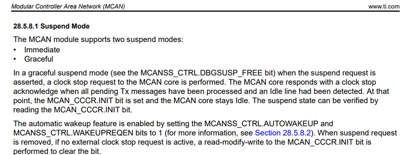
    Your code looks good. In normal execution mode, you saw the TX message and the RX message (entering RX ISR). I think you enabled the "debug suspend" in CANSS_CTRL register. The Suspend mode prevents the interrupt requests from propagating to the Host CPU.

    Please refer to the section 28.5.8.1 (suspend Mode)

  • Hi Qj,

    Thanks for the update. I can confirm the issue was there is a option to enable debug suspend in the syscfg file.

    Siu