This thread has been locked.

If you have a related question, please click the "Ask a related question" button in the top right corner. The newly created question will be automatically linked to this question.

TMS320F28379D: Issues with DMA Transfer to SPI TX in FIFO

Part Number: TMS320F28379D
Other Parts Discussed in Thread: SYSCONFIG

Hello all,

I am working on a project where we would like to use the F28379D as a peripheral over SPI. To this end we are trying to configure the device to use DMA. Our current test setup is a Raspberry Pi as the controller and the F28379D as the peripheral. Currently, we are doing all testing on core one to avoid memory/peripheral ownership issues.

We have verified this setup works by using the write/read blocking commands and have succesfully completed transactions with the current settings. To start, we used the SPI and DMA examples provided by TI to guide our implementation.  

Attached is a minimal example using the driverlib and sysconfig where the DMA transfer works on trigger from SPI TX interrupt if we transfer to an interal buffer (use #define ALT_EXAMPLE), but when we try to transfer to the SPI TX FIFO buffer we get garbage data. Additionally, we have an interrupt set to occur after the DMA transaction completes and can confirm it happens in either case. 

As far as we can tell this indicates the trigger is correct (since TX isn't filled we repeatedly trigger the DMA until it's fully transfered to the example_buf in the ALT_EXAMPLE). It also indicate the SRC pointer is correct since the correct data appears in example_buf.

Additionally, we are following guidance of ```18.2.8.2 Receiving Data Using SPI with DMA``` and have RXFFIL set to 8 samples and DMA_BURST_SIZE set to 7.

Hopefully there is a small issue in our configuration as we are not sure where next to go to debug the issue. Thank you for any help.


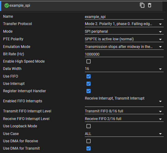
SPI Config in Sys Config:
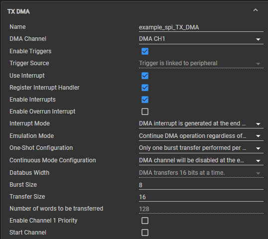
image.png

DMA Config:

image.png


SRC and DEST of DMA are configured in code (exerpt from empty_driverlib_main.c):

    #ifdef ALT_EXAMPLE
    DMA_configAddresses(example_spi_TX_DMA_BASE, example_buf,  test_buf);
    DMA_configBurst(example_spi_TX_DMA_BASE, 8, 1, 1); // Burst Size, Src step, dest step 
    DMA_configTransfer(example_spi_TX_DMA_BASE, 16,  1, 1); // Transfer Size, Src Step, dest step 
    #else
    DMA_configAddresses(example_spi_TX_DMA_BASE, example_spi_TX_DMA_ADDRESS,  test_buf);
    DMA_configBurst(example_spi_TX_DMA_BASE, 8, 1, 0); // Burst Size, Src step, dest step (Notice how dest step is zero)
    DMA_configTransfer(example_spi_TX_DMA_BASE, 16,  1, 0); // Transfer Size, Src Step, dest step (Again, notice step is zero)
    #endif
    DMA_startChannel(example_spi_TX_DMA_BASE);


Driverlib Empty CPU1 Example CCS Project.zip 


  • Hi Bendik,

    I don't see any apparent issues with your setup. 

    when we try to transfer to the SPI TX FIFO buffer we get garbage data

    How are you checking this? Are you scoping the MISO pin and the data there looks to be garbage? Can you send the values of the SPI registers (with Continuous refresh toggled on) when you are paused inside the end of transfer DMA ISR? I can take a look and see if anything seems off with the state of the SPI after the transfer.

    Also, do you have any other DMA channels enabled in your application when you are testing this?

    Best Regards,

    Delaney

  • Hi Delaney,

    We are checking this on a Raspberry Pi and have verified the configuration with a scope. Specifically, we did testing without DMA to ensure that data could be transmitted correctly, and now, using those settings, we have moved to using a Raspberry Pi

    It might be incorrect to say the data is garbage; the data returned is mostly consistent across transactions. So whatever data is returned the first time will usually be repeated. We will see some values change, but that may be because this is prototyped and we misread the bit.

    In all cases, the first two words we insert (0x00 and 0xAA) are always read correctly, followed by the described behavior.

    Here are the SPI register states:

    SPICCR    0x00CF    0x00006100@Data    SPI Configuration Control Register
    SPICTL    0x0002    0x00006101@Data    SPI Operation Control Register
    SPISTS    0x0000    0x00006102@Data    SPI Status Register
    SPIBRR    0x0031    0x00006104@Data    SPI Baud Rate Register
    SPIRXEMU    0x7FFF    0x00006106@Data    SPI Emulation Buffer Register
    SPIRXBUF    0x240A    0x00006107@Data    SPI Serial Input Buffer Register
    SPITXBUF    0x00AA    0x00006108@Data    SPI Serial Output Buffer Register
    SPIDAT    0x00AA    0x00006109@Data    SPI Serial Data Register
    SPIFFTX    0xE0A8    0x0000610A@Data    SPI FIFO Transmit Register
    SPIFFRX    0x2022    0x0000610B@Data    SPI FIFO Receive Register
    SPIFFCT    0x0000    0x0000610C@Data    SPI FIFO Control Register
    SPIPRI    0x0000    0x0000610F@Data    SPI Priority Control Register

    Additionally DMA register states:

    MODE    0x8301    0x00001020@Data    Mode Register
    CONTROL    0x0100    0x00001021@Data    Control Register
    BURST_SIZE    0x0007    0x00001022@Data    Burst Size Register
    BURST_COUNT    0x0000    0x00001023@Data    Burst Count Register
    SRC_BURST_STEP    0x0001    0x00001024@Data    Source Burst Step Register
    DST_BURST_STEP    0x0000    0x00001025@Data    Destination Burst Step Register
    TRANSFER_SIZE    0x000F    0x00001026@Data    Transfer Size Register
    TRANSFER_COUNT    0x0000    0x00001027@Data    Transfer Count Register
    SRC_TRANSFER_STEP    0x0001    0x00001028@Data    Source Transfer Step Register
    DST_TRANSFER_STEP    0x0000    0x00001029@Data    Destination Transfer Step Register
    SRC_WRAP_SIZE    0xFFFE    0x0000102A@Data    Source Wrap Size Register
    SRC_WRAP_COUNT    0xFFEE    0x0000102B@Data    Source Wrap Count Register
    SRC_WRAP_STEP    0x0000    0x0000102C@Data    Source Wrap Step Register
    DST_WRAP_SIZE    0xFFFE    0x0000102D@Data    Destination Wrap Size Register
    DST_WRAP_COUNT    0xFFEE    0x0000102E@Data    Destination Wrap Count Register
    DST_WRAP_STEP    0x0000    0x0000102F@Data    Destination Wrap Step Register
    SRC_BEG_ADDR_SHADOW    0x0000C000    0x00001030@Data    Source Begin Address Shadow Register
    SRC_ADDR_SHADOW    0x0000C000    0x00001032@Data    Source Address Shadow Register
    SRC_BEG_ADDR_ACTIVE    0x0000C000    0x00001034@Data    Source Begin Address Active Register
    SRC_ADDR_ACTIVE    0x0000C080    0x00001036@Data    Source Address Active Register
    DST_BEG_ADDR_SHADOW    0x00006108    0x00001038@Data    Destination Begin Address Shadow Register
    DST_ADDR_SHADOW    0x00006108    0x0000103A@Data    Destination Address Shadow Register
    DST_BEG_ADDR_ACTIVE    0x00006108    0x0000103C@Data    Destination Begin Address Active Register
    DST_ADDR_ACTIVE    0x00006108    0x0000103E@Data    Destination Address Active Register

    Please let me know if there is a better way to export this for you. I used the Registers tab, selected each column in SpiaRegs, and copied and pasted it into this window.

    In both the larger program and the recreated example that I attached, only this DMA channel is active. 

  • Hi Bendik,

    Thank you for sending the register export, I will look through your settings and get back to you.

    Best Regards,

    Delaney

  • Hi Bendik,

    Apologies for the delay here. A couple notes:

    Can you try removing the Interrupt_disable() and Interrupt_enable() calls during your program execution? I would recommend only using these during initialization; I've seen them cause issues sometime when used in the regular program flow. Are you trying to one at a time switch between getting an RX interrupt and doing a TX DMA transfer? If so, can you try using a global state variable to keep track of which operation should be happening?

    For example, if the global variable was called txdma and was initialized =0. Inside the RX interrupt, you can put a check for txdma==0 before executing any of the code, besides clearing the SPI interrupt status and ACKing the interrupt, those should always be there. txdma can be set to 1 right before the DMA channel is started/restarted. Then clear txdma inside the end of transfer ISR. Let me know if this would be feasible.

    There also may be some issue with timing going on since the SPI is the peripheral device and doesn't control when transactions happen. Can you try enabling the overrun error interrupt and adding a breakpoint inside the ISR to see if overrun is ever being flagged? Unfortunately, it looks like we don't have any SPI DMA examples in SPI peripheral mode. I will try this out myself, but in the meantime, please see if either of the above suggestions improve anything and let me know. 

    Best Regards,

    Delaney

  • Hi Delaney,

    I followed the first suggestion and removed the Interrupt_disable() and Interrupt_enable() calls. We then tried sending our request from the master, but we again received garbage data. The garbage data was different from before: it initially contained random numbers, then zeroed out for the rest of the transmission. For debugging, I think this solution is fine, and it may work as the application matures. (We anticipate being cycle limited, but have yet to have that happen.)

    Ideally, we would turn off interrupts on the RX during data transmission. Since we transmit 256-word packets, we would generate at least 256/16 (16 interrupts) additionally per transmission. While some overhead could be avoided through optimization, I think we would be better off not using DMA for transmission if we need to keep the RX interrupt to get DMA working.

    We currently use RX/TX interrupt without DMA, which unfortunately incurs TX interrupts to keep the TX buffer filled. This strategy disables the RX interrupt during data transmission. In comparison, this would free up another DMA channel while incurring a similar interrupt penalty. Overall, this should be faster, since the DMA could be used elsewhere to save additional cycles. 

    As an aside, we had initial issues getting interrupt_enable/disable to work. We found that resetting the SPI RX FIFO buffer was required before re-enabling the SPI RX interrupt; otherwise, the interrupt would not trigger. 

    Using the new setup, we also checked the RXFFOVF (Receive FIFO Overflow Flag), and it was not raised. This was not expected. In the current code, the RX is not cleared until the TX DMA finishes. As such, we should overflow many times without the RX ISR being serviced to clear the FIFO buffer. I understand this is not the approach you recommended. If this is an incorrect way to check for an overflow, please let me know, and I'll set it up as you described.

    Modified Code:8156.Driverlib Empty CPU1 Example CCS Project.zip

  • Hi Bendik,

    I'm still working on testing your code myself but will get back to you with an update tomorrow. 

    Best Regards,

    Delaney

  • Hi Bendik,

    To update, I have been able to replicate the behavior you described on my setup with your most recent code. I am still looking into the issue.

    Best Regards,

    Delaney

  • Hi Bendik,

    To update, I am still actively debugging this. I'm trying to get a simple example with two SPI instances to work where the peripheral device uses DMA to transmit. It appears the SPI_TX_DMA trigger logic may be different than I would expect, I will keep looking into it and update you next week.

    Best Regards,

    Delaney

  • Hi Delaney,

    Just to clarify, do you mean different than as specified in the SPRUHM8K in sections 18.2.4 DMA Support and 18.3.8.1 SPI DMA Transfers?

  • Hi Bendik,

    The settings I'm using to test were calculated according to how the SPI/DMA TRM sections advise, I'm just having trouble getting the SPI TX DMA trigger to work properly with the SPI in slave mode. I know your code was able to trigger the DMA but wasn't resulting in the correct transmission from the SPI slave. I'm still trying to piece together the behavior in each case. Please allow me some more time to debug this, I may need to discuss with the design team. I will update at the end of the week. 

    Best Regards,

    Delaney

  • Hi Bendik,

    I apologize for the delay. I think I have figured out your issue, or at least part of the issue. On this device, for the DMA to be able to access the SPI registers, the DMA needs to be configured as the secondary master in the SECMSEL register for peripheral frame 2. See TRM section here describing this. Without this configuration, DMA writes to the SPI registers will not take effect. 

    Can you try adding the below code to your initialization and let me know if it solves the issue:

        SysCtl_selectSecController(SYSCTL_SEC_CONTROLLER_DMA, SYSCTL_SEC_CONTROLLER_DMA);
    

    Best Regards,

    Delaney

  • Hi Delaney,

    Thank you for looking into this issue. Adding this code segment immediately after Board_init() made the example work correctly. 

    For future users, or perhaps myself if I forget:

    The SPI peripheral must be configured following 18.2.4 (DMA Support)

    The DMA peripheral must be configured as described in 18.3.8 (SPI DMA Transfers)

    Finally, SECMSEL and the CPUSEL for the SPI Peripheral device should be configured for the target DMA peripheral.

    Attached is the working example.

    4520.Driverlib Empty CPU1 Example CCS Project.zip

  • Hi Bendik,

    Glad to hear that fixed the issue! I have filed a bug for Sysconfig about this so that the line is autogenerated in future releases when DMA support is added with SPI. I will close this thread but please feel free to make another one if you have any further questions. 

    Best Regards,

    Delaney