This thread has been locked.

If you have a related question, please click the "Ask a related question" button in the top right corner. The newly created question will be automatically linked to this question.

TMS320F280038C-Q1: Unexpected ADC interrupt period deviation

Part Number: TMS320F280038C-Q1

Hello,

I have a perfectly functioning digital power control board. To measure the time spent on an ADC interrupt, I added `gpio=high` to the beginning and end of routines, and `gpio=low` to the end of routines. No other function uses this GPIO. In the project, I use ADC interrupts and CAN receive interrupts.

An ADC interrupt is triggered at every 30 usec. I calculate required controller effort at this interrupt.

A CAN interrupt is triggered when a message arrives.

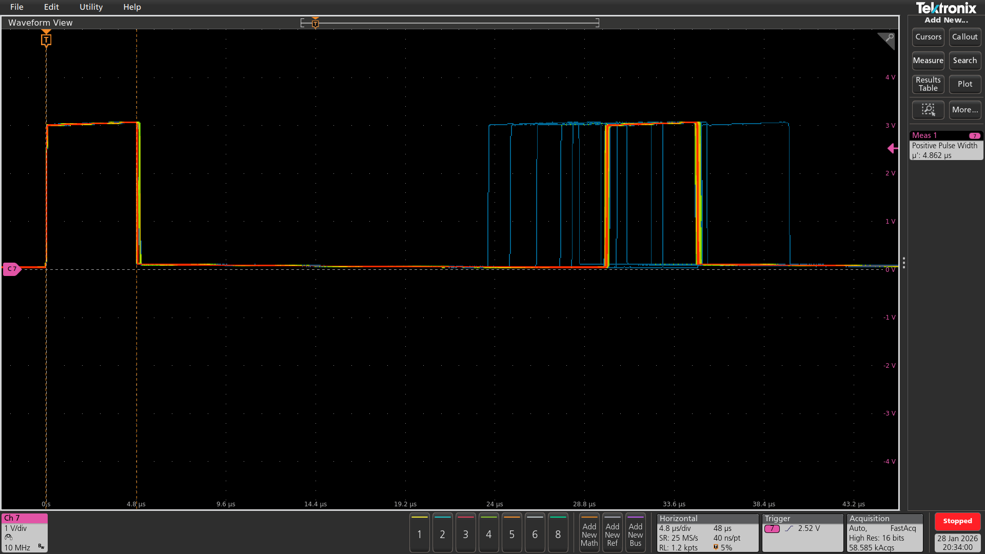
I started examining the oscilloscope in high-acquisition mode and noticed that my ADC interrupt trigger time changes frequently. I added image.

1) How can I identify the root cause of this? What do you suggest?

2) What are some possible factors that could be causing this?

3) Is there a register set I can use to track this with debugging?
 isr_000.png


  • Hi Gokhan,

    What you’re seeing on the scope is very often interrupt service latency/jitter, not the ADC trigger itself moving. Toggling a GPIO at the beginning/end of the ADC ISR measures when the CPU starts servicing the interrupt, which can shift if any other ISR is executing or if global interrupts are disabled for short windows.

    On C2000, when you enter an ISR, the CPU typically sets INTM=1 (global interrupts masked) until you return. So if a CAN message arrives close to your 30 us ADC interrupt, the ADC ISR will be serviced late, causing the apparent period deviation on the GPIO pulse train.

    Even if ADC is higher priority logically, it still cannot run until the currently executing ISR finishes unless you explicitly implement interrupt nesting.

    Best Regards,

    Masoud

  • Hi Masoud,

    Thank you for your clear answer.

    As a designer when I read following sentence at usermanual, I wouldn't expect such behaviour. Is it an errata?

    "

    3.5.5 PIE Channel Mapping
    Table 3-3 shows the PIE group and channel assignments for each peripheral interrupt. Each row is a group, and each column is a channel within that
    group. When multiple interrupts are pending, the lowest-numbered channel is the lowest-numbered group is serviced first. Thus, the interrupts at the top
    of the table have the highest priority, and the interrupts at the bottom have the lowest priority.

    "

    In order to solve the problem, how can I implement interrupt nesting? Do you recommend any example sw if available at c2000 ware.

  • Hi Gokhan,

    This is expected behavior, not an errata. That PIE channel mapping / priority text describes which pending interrupt will be serviced first when the CPU is free to take an interrupt. On C28x, once the CPU vectors into an ISR, the CPU sets the global interrupt mask (INTM=1) by default, so no other maskable interrupt can preempt until you either return from the ISR or explicitly re-enable interrupts inside the ISR nesting. So if a CAN RX ISR happens to be executing when your 30 us ADC interrupt becomes pending, the ADC ISR start time will shift later then exactly the period deviation you’re seeing on the GPIO timing measurement.

    For nesting, you can refer to this article:

    https://software-dl.ti.com/C2000/docs/c28x_interrupt_nesting/html/index.html

    Best Regards,

    Masoud

  • If you truly need ADC always on-time, enable interrupt nesting in the lower-priority ISR (CAN). This allows higher-priority ADC to preempt CAN. This is the standard approach for periodic fast-response (ADC/control loop) vs buffered serial (CAN) workloads.

    Best Regards,

    Masoud