This thread has been locked.

If you have a related question, please click the "Ask a related question" button in the top right corner. The newly created question will be automatically linked to this question.

TMS320F28388D: UART Interface to the GSM Interface

Part Number: TMS320F28388D

Dear Team,

We are currently using the PN: F28388DPTPSR for our development.

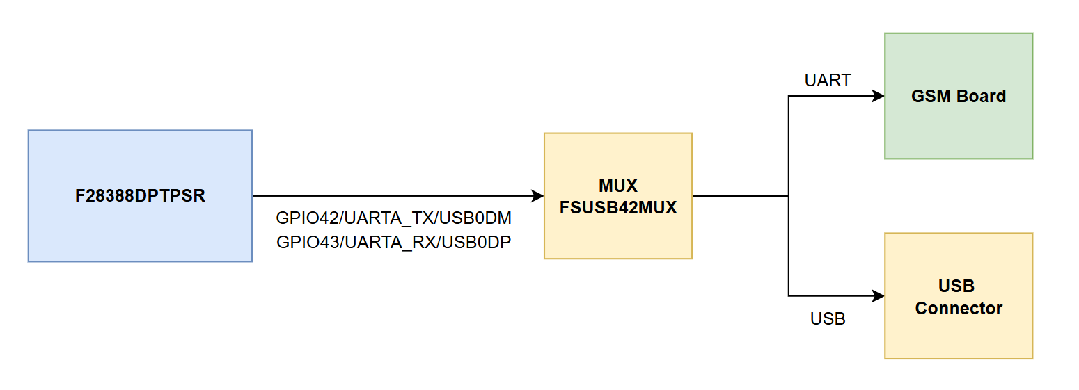
We have connected the debug pins GPIO42 (UARTA_TX) and GPIO43 (UARTB_RX) to our GSM module. At the same time, we are using a MUX to switch between UART and USB.

Please find the attached image for your reference. 

image.png

We have the following queries:

  1. Can we continuously send data on UARTA to the GSM module during runtime?
  2. Will there be any issues while switching between UART and USB using the MUX?

Kindly clarify. Thanks in advance


Regards,

Praveen 

  • Hi Praveen,

    I'm a little confused by this topology. Do you have a UART-to-USB bridge anywhere in the topology? How are the UART outputs getting converted to the USB protocol?

    Best Regards,

    Delaney

  • Dear Delaney Woodward. 

    Thanks for your response. 

    The GPIO42 and GPIO43 support both USB and UART - It can be controlled by the internal mux in the MCU. 

    Datasheet: Page No 29:

    Regards

    Praveen 

  • Hi Praveen,

    I see, so you are wanting to switch the device pinmux during runtime between the UART and USB peripherals. From a peripheral point of view, you generally don't want to configure the GPIOs for a specific peripheral while the peripheral is enabled/operating. You would want to disable both peripherals before modifying the related pinmux selections to switch to the other peripheral in order to keep both the UART and USB peripherals in a known state.

    For UART specifically, you will also want to make sure this pinmux switch is synchronized with the UART operation / make sure the GSM doesn't send anything while the GPIOs are configured for the USB because the data would be lost. To send continuous data during runtime to the GSM, I would suggest using the DMA module with the UART, so the CPU isn't bogged down with every UART write. A continuous stream of data should be possible on the UART module as long as the FIFO is never left empty at any point. To do this, I would suggest using the UART_TX DMA trigger and transferring >8 bytes of data at a time so that the DMA consistently fills up the UART TX FIFO. 

    I am looping in the GPIO expert to comment on if there are any issues with constantly switching settings during runtime from a pinmux standpoint. 

    Best Regards,

    Delaney

  • Hi Praveen,

    I don't see any issues with this approach from a pinmux perspective. Like Delaney mentioned, it's best to completely disable the modules before switching to the other communication peripheral. From a hardware design perspective, to ensure best USB performance, you will want to make sure the signal from the MCU GPIOs to the USB switch are differentially routed and impedance matched. Past the USB switch, only the USB signals need to be differential/impedance matched, but you can also make the UART as well since that typically doesn't increase the board cost further.

    Regards,

    Peter

  • Dear Peter and Delaney, 

    Thank you for your input.

    Can we use GPIO84 and GPIO85 for the UART interface? So we can avoid the MUX. 

    My concern is that GPIO84 functions as a BOOT pin for the device. If we configure it for UART, will it impact the boot operation? Currently, we are using CAN boot mode.

    Please confirm whether these two pins can be safely used for the UART interface without affecting the boot process.

    Thanks in advance.

    Regards, Praveen. 

  • Hi Praveen,

    GPIO84 is one of the default boot mode select pins. With the default pins used, you would need to have GPIO84 tied low during boot time to select the CAN boot mode. The pin would basically need to be an input that is tied low during boot time then reconfigured to an idle-high output during runtime for the UART. Let me check with a colleague about if there are any risks associated with this.

    Another option is that you can change the BMSP pins by modifying the OTP memory. See guide here for how to do this. On the F2838x you would need to write the BOOTPIN-CONFIG and BOOTDEF registers.

    Best Regards,

    Delaney

  • Hi Praveen,

    If you want to keep GPIO84 as your boot pin, you can just add a weak pull-down resistor (something like 10kohms) so that the pin is pulled low during boot time and the device boots with the CAN boot mode. Then, in your main sequence, you can reconfigure GPIO84 for UART TX operations from the pinmux (output) and you'll just need to make sure the drive strength is less than 4mA, as specified in the datasheet.

    If you don't want to add the external component, you can change the BMSP pin as I described in my previous reply. Please upvote this response if it answers your question. Slight smile

    Best Regards,

    Delaney

  • Dear Delaney, 

    Noted, Thanks for your support.