This thread has been locked.

If you have a related question, please click the "Ask a related question" button in the top right corner. The newly created question will be automatically linked to this question.

SM320F28335-EP: SM320F28335-EP, Flash Programming Issue

Part Number: SM320F28335-EP
Other Parts Discussed in Thread: TMS320F28335, C2000WARE, , TMP1075

Hello TI Community,

I am working on a TMS320F28335 based ECU project using Code Composer Studio (CCS) and I have been struggling with a Flash execution issue. I would really appreciate your help.

   My Setup:

  • Device: SM320F28335- EP
  • IDE: Code Composer Studio (CCS) v20.3.1.5
  • Build Mode: FlasH
  • Peripherals Used: CAN-A, I2C-A, SPI (EEPROM), ADC, ePWM, GPIO


 Problem:

  • Code runs perfectly in RAM debug mode
  • When I load the same code to Flash, the device STOP at ILLIGAL_ISR , hangs or crashes during initialization
  • The CPU does not reach the while(1) main loop


ECUV3 FLASH.c (2).zipScreenshot 2026-03-02 144926.png

  • Take a look at this example: C:\ti\c2000\C2000Ware_6_00_00_00\device_support\f2833x\examples\flash_f28335. 

    When you run from flash, there can be(and likely is) a region of your code that is still mapped to SRAM.  The reason for doing so, is that the RAM can run at the full 150MHz, while flash memory is waitstated, usually ISRs are maintained in RAM.

    Anyway, in the .cmd file you should see a section of code (usually call ramfuncs or tiramfuncs), that has a load to flash, but run from RAM.  However, this is only one part of what needs to happen.  The other part is in your setup code, there should be a function call to memcopy; where the code is copied from flash to RAM, before it can run.

    If this is missing, then the RAM will not have any code, and when your program attempts to execute the program code, it will get an illegal op-code, hence the illegal ISR.

    At any rate, look at both the example code and .cmd in the above path, and correct your code accordingly/

    Best,

    Matthew

  • Hello Matthew Pate,

    Today, I imported the flash_f28335. example code and tried to program it to the MCU. However, I am still facing the same issue — the program is going to an Illegal ISR.

    As suggested, I am using the same flash.cmd file from the Flash example project. In my main application code, I have implemented the configuration exactly as shown in the Flash example, but the issue is still not resolved.

    For your reference, I have attached my main.c, flash.cmd, and the complete project files ( . Could you please review them and help me identify what might be causing this issue?

    Thank you for your support.

    code link

    or https://drive.google.com/drive/folders/12BsnElCT1Or0PcHcupE04FwNJmn2kfw-?usp=drive_link

  • Harsh,

    I'm still looking through the project/source you uploaded, nothing I've identified so far.  

    On you PCB can you confirm the input clock frequency to the device?  I want to rule out over-clocking as a possible root cause here.

    Best,

    Matthew

  • Hello Matthew,

    Thank you for checking the project and source files.

    On our PCB, we are using a 25 MHz crystal clock as the input clock for the SM320F28335-EP device. Please let me know if you need any additional hardware details or measurements from our side.

    Best regards,
    Harsh

  • Harsh,

    I think there may be a very subtle code issue in play.  For the memory copy you are calling:

    memcpy(&RamfuncsRunStart, &RamfuncsLoadStart, (Uint32)&RamfuncsLoadSize);

    which is the C standard library function.

    Can you replace this with the TI defined function:

    MemCopy(&RamfuncsLoadStart, &RamfuncsLoadEnd, &RamfuncsRunStart);

    and see if this fixes things.

    Best,

    Matthew

  • Hi Matthew,
    Thank you for your suggestion.
    I have already replaced the memcpy function with the TI-defined MemCopy(&RamfuncsLoadStart, &RamfuncsLoadEnd, &RamfuncsRunStart); as you recommended.
    I verified that when flashing in debug mode, the code is working fine.
    However, when I power off the board and power it back on, the system is not booting properly.
    Kindly confirm whether the PLL configuration values are correct. I am using a 25 MHz crystal for the system clock.
     I will continue debugging, but please let me know if there are any additional checks or suggestions you would recommend.
    #define DSP28_PLLCR  4
    #define DSP28_DIVSEL     1
    #define CPU_RATE   10.000L   // for a 100MHz CPU clock speed (SYSCLKOUT)
    void main(void)
    {
    // Initialize System Control
        InitSysCtrl();
       
        // Disable CPU interrupts
          DINT;
          InitPieCtrl();
          IER = 0x0000;
          IFR = 0x0000;
                 MemCopy(&RamfuncsLoadStart, &RamfuncsLoadEnd, &RamfuncsRunStart);
     
        // //
        // // Call Flash Initialization to setup flash waitstates
        // // This function must reside in RAM
        // //
         InitFlash();


        InitPieVectTable();
     
    Thanks and regards,`
    Harshath Gowda 
  • Harshath,

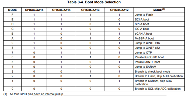
    Can you check the below boot pins, to make sure they are all pulled "high" on your board to invoke the boot to flash

    Also, a small correction to your PLL settings.

    Currently you have specified a PLLCR = 4(multiply by 4) with a DIVSEL = 1(this divides by 4) so you are going to end up with 25MHz SYSCLK.

    For 100MHz you need to use these settings:

    #define DSP28_PLLCR  8
    #define DSP28_DIVSEL     2
    This will give 25MHz * 8/2 = 100MHz.
    I think what you intended with your original settings was 25 *4/1.  DIVSEL = 3 in this case...however, we don't allow the /1 (DIVSEL = 3) if the PLL is in use, we must use either /2 or /4.
    Let me know.
    Best,
    Matthew
  • Hi Matthew,
    Thank you for your suggestion.
    I updated the PLL settings as you mentioned (PLLCR = 8 and DIVSEL = 2). However, with these values, the code stops at an illegal ISR.
    When I use the following settings:

    #define DSP28_PLLCR 6
    #define DSP28_DIVSEL 2
    the code runs without any issues.
    I also observed that when I program the flash and run the code in debug mode, it works fine. However, after power cycling (turning the supply OFF and ON), the code does not boot properly from flash.
    Could you please help me understand why this issue is occurring?
    Thanks and regards,
    Harshath
    9743346482
  • Harshath,

    Can you attach your latest code source via drive like you did before?

    Best,

    Matthew

  • Hi Matthew,
    Please refer to the same code base I shared earlier via Drive. I have only made changes in the main function and updated some PLL values. For your reference, I have attached the updated code below.
    With the current configuration, the flash is working fine and I am not facing any issues. As you know, my external oscillator frequency is 25 MHz. I am trying to run the system clock at 125 MHz or 150 MHz.
    Could you please guide me on how to properly configure the system to achieve 150 MHz SYSCLK? If any changes to the clock crystal or configuration are required, please let me know—we are ready to make the necessary modifications.
    Additionally, while debugging this issue, I did mistake and internal watchdog was enabled every 5 ms  on both MCUs, are reset  and we have replaced the MCU as part of troubleshooting.
    I am looking forward to your guidance on achieving stable operation at 150 MHz in flash boot mode.
    Best regards,
    Harshath.. 
     
    // // Functions that MUST run from RAM (flash power manipulation or time-critical)
     #ifdef __TI_COMPILER_VERSION__
        #if __TI_COMPILER_VERSION__ >= 15009000
            #pragma CODE_SECTION(ecana_isr, ".TI.ramfunc");
    //         // Add any other ISRs here that touch flash power registers
        #else
          #pragma CODE_SECTION(ecana_isr, "ramfuncs");
         #endif
     #endif
     
     
    // // These are defined by the linker (see F28335.cmd)
    // //
     extern Uint16 RamfuncsLoadStart;
     extern Uint16 RamfuncsLoadEnd;
     extern Uint16 RamfuncsRunStart;
     extern Uint16 RamfuncsLoadSize;


    Uint16 write_word = 0x1234;
    Uint16 read_word = 0;
      Uint16 abc = 0;
    void main(void)
    {
        // Variable declarations
         uint16_t i;
        Uint32 txMailboxes[2] = {1, 2};
        Uint32 txIDs[2] = {0x100, 0x101};
        int tmp1075_status;
       
        // Initialize System Control
        InitSysCtrl();
       
        // Disable CPU interrupts
          DINT;
          InitPieCtrl();
          IER = 0x0000;
          IFR = 0x0000;
        MemCopy(&RamfuncsLoadStart, &RamfuncsLoadEnd, &RamfuncsRunStart);
     
          InitFlash();


        InitPieVectTable();
     
        // Setup interrupt vectors
        EALLOW;
        PieVectTable.ECAN0INTA = &ecana_isr;
        //PieVectTable.I2CINT1A = &i2c_int1a_isr;
        SysCtrlRegs.PCLKCR0.bit.ECANAENCLK = 1;
        SysCtrlRegs.PCLKCR0.bit.I2CAENCLK = 1;  // Enable I2C clock
        EDIS;
     
  • Harsh,

    1)In your Ecanmain.c here is the correct syntax for the TI MemCopy(you may have already done this, but just being complete)

     MemCopy(&RamfuncsLoadStart, &RamfuncsLoadEnd, &RamfuncsRunStart);

    This has different arguments than memcpy which takes start, load start and load size.  I think as long as you had given memcpy the correct variables it might be OK as well, but lets stick to the above.

    2)DSP2833x_Examples.h lines 53 - 71 should look like this for 10MHz input clock with desired 100MHz SYSCLK

    // Specify the PLL control register (PLLCR) and divide select (DIVSEL) value.
    //
    //#define DSP28_DIVSEL   0   // Enable /4 for SYSCLKOUT
    //#define DSP28_DIVSEL   1 // Enable /4 for SYSCKOUT
    #define DSP28_DIVSEL     2 // Enable /2 for SYSCLKOUT
    //#define DSP28_DIVSEL     3 // Enable /1 for SYSCLKOUT
    
    //#define DSP28_PLLCR   10
    //#define DSP28_PLLCR    9
    #define DSP28_PLLCR    8
    //#define DSP28_PLLCR    7
    //#define DSP28_PLLCR    6
    //#define DSP28_PLLCR    5
    //#define DSP28_PLLCR    4
    //#define DSP28_PLLCR    3
    //#define DSP28_PLLCR    2
    //#define DSP28_PLLCR    1
    //#define DSP28_PLLCR    0  // PLL is bypassed in this mode
    

    and lines 103 -113 are this to set the clock to 10ns period

    //#define CPU_RATE    6.667L   // for a 150MHz CPU clock speed (SYSCLKOUT)
    //#define CPU_RATE    7.143L   // for a 140MHz CPU clock speed (SYSCLKOUT)
    //#define CPU_RATE    8.333L   // for a 120MHz CPU clock speed (SYSCLKOUT)
     #define CPU_RATE   10.000L   // for a 100MHz CPU clock speed (SYSCLKOUT)
    //#define CPU_RATE   13.330L   // for a 75MHz CPU clock speed (SYSCLKOUT)
    //#define CPU_RATE   20.000L   // for a 50MHz CPU clock speed  (SYSCLKOUT)
    //#define CPU_RATE   33.333L   // for a 30MHz CPU clock speed  (SYSCLKOUT)
    //#define CPU_RATE   41.667L   // for a 24MHz CPU clock speed  (SYSCLKOUT)
    //#define CPU_RATE   50.000L   // for a 20MHz CPU clock speed  (SYSCLKOUT)
    //#define CPU_RATE   66.667L   // for a 15MHz CPU clock speed  (SYSCLKOUT)
    //#define CPU_RATE  100.000L   // for a 10MHz CPU clock speed  (SYSCLKOUT)

    Now at line 120 - 126 you will see a #if(compile time if) that is looking for a device definition to define if the device is 150MHz or 100MHz. 

    #if DSP28_28332 || DSP28_28333  // 28332 and 28333 devices only
      #define CPU_FRQ_100MHZ  1     // 100 Mhz CPU Freq (20 MHz input freq)
      #define CPU_FRQ_150MHZ  0
    #else
      #define CPU_FRQ_100MHZ  0  // DSP28_28335||DSP28_28334
      #define CPU_FRQ_150MHZ  1  // 150 MHz CPU Freq (30 MHz input freq) by DEFAULT
    #endif

    We can use this to our advantage, since you are clocking at 100MHz anyway(even if you have a device capable of 150MHz), as the #if is used in some other places to scale the clock.  However, the control for this is not a pre-define, but inside DSP2833x_Device.h, and after we make this change and re-compile we want to see the 100MHz #define become ungreyed.  Lines 61-64 of Device.h

    #define   DSP28_28335   0        // Selects '28335/'28235
    #define   DSP28_28334   0         // Selects '28334/'28234
    #define   DSP28_28333   0         // Selects '28333/'
    #define   DSP28_28332   TARGET         // Selects '28332/'28232

    This should set up both the code and placement to work correctly.  I've verified that the code is getting placed correctly at the Flash entry point of 0x33 FFF6 - 0x33 FFF7, and will eventually call main.  I've also verified that the code correctly copies the RAM and executes from it.

    As long as the boot mode pins are set correctly to Boot to Flash, then the code we see during debug should match exactly what will run standalone.

    Best,
    Matthew