This thread has been locked.

If you have a related question, please click the "Ask a related question" button in the top right corner. The newly created question will be automatically linked to this question.

TMS320F28384D: PWM Shadow Register Contention

Part Number: TMS320F28384D
Other Parts Discussed in Thread: SYSCONFIG

Hello,

I am experiencing what I think is some contention of shadow registers being loaded when I am transitioning my PWM outputs from completely off to Active High Complementary.  I am altering both DBCTL and AQCTLA/B registers which are configured to both load on a SYNCIN event via the Global Load registers.

Here are the steps I take to turn off the PWM outputs and then turn them on again.

To turn off:

  1. Set DBCTL.OUT_MODE to 2, to bypass the deadband module on output B
  2. Set all AQCTLA and AQCTLB to 1 so that the output clears on all events

To turn them on:

  1. Set DBCTL.OUT_MODE to 3, to re-enable deadband on output B
  2. Set AQCTLA to SET the output at TBCTR = ZRO
  3. Set AQCTLA to SET the output at TBCTR = CAD
  4. SET AQCTLA to CLEAR the output at TBCTR = CAU
  5. All other AQCTLA registers are set to No Action.

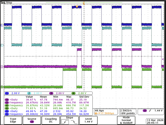
The result is that my PWMs do exactly what I want except for a small 8-12ns blip on output B when transitioning from OFF, circled in red in my image.  The measurement from the blip to when its corresponding A channel gets flipped high is exactly the time of my deadband setting of 1 microsecond.

Is there some sort of order that the processor follows for what shadow registers get loaded when?  This behavior would be explained if the deadband shadow registers got loaded before the action qualifer registers because with Active High polarity, output B would want to turn on if A is low.  Is this expected behavior or is there another way I could turn on/off the PWMs to avoid this blip?

image.png

Thanks,

Will

  • Will,

    This issue can be resolved by setting AQCLTA and AQCTLB as shadowed register. By default these register are immediate load. The 8-12ns blip you're observing is caused by the AQCTLA and AQCTLB registers not being shadowed (i.e. immediate), meaning they update immediately upon write rather than synchronizing with SYNCIN events (which is the case with shadow loading). Also, ePWM module signal path in TRM shows that the Action-Qualifier (AQ) submodule output feeds into the Dead-Band (DB) submodule. This creates a timing mismatch where the Action-Qualifier registers take effect before the Dead-Band control register, causing output B to briefly activate when output A is low during the transition.

    Another clean solution to turn on and off PWM: Instead of manipulating the Action-Qualifier registers to turn outputs on/off, use the Trip-Zone (TZ) submodule, which is downstream from the Dead-Band module in the signal path. This approach keeps your Action-Qualifier and Dead-Band configurations constant and uses TZ to force outputs to a known state (high, low, or high-impedance) along with providing synchronized control without the timing issues.

    Let me know if these resolutions works for you.

    Regards,

    Sumit

  • Hi Sumit,

    Thanks for your reply.  I do have AQCTLA and AQCTLB as shadow registers to be loaded by SYNCIN event by configuring:

    AQCTL.SHDWAQAMODE and AQCTL.SHDWAQBMODE to 1
    AQCTL.LDAQASYNC and AQCTL.LDAQBSYNC to 2

    I want everything to be updated on a SYNCIN event which is supplied by a different PWM acting as our timer.  From what I can tell, everything seems to be correctly updated on a SYNCIN event because I have a GPIO being toggled at the rate of my SYNCIN signal, and it aligns with our PWM changes.

    I will look into the Trip Zone module but ideally I want everything to be turned on/off at the SYNCIN boundary and the TZ module seems to be immediate.  I'll have to investigate if that will work for us.  

    But, now that you know I have AQCTL configured as a shadow register, do you know what else could cause this blip? Could it be because the Deadband registers rely on the Global Load settings to load on SYNCIN, whereas the AQCTL registers have their own SYNCIN setting and don't use Global Load?

  • Will,

    I think your analysis is correct - this is indeed a shadow register loading sequence issue. The glitch occurs because DBCTL and AQCTL registers are not loading simultaneously during the SYNCIN event, despite both being configured for SYNCIN-based sequential loading. The proper solution is to use the Global Load functionality for both to ensure DBCTL and AQCTL registers load simultaneously on the SYNCIN event.

    You can follow the sequence as shown below and see if issue resolves:

    // Step 1: Enable Global Load for DBCTL register
    EPWM_enableGlobalLoadRegisters(base, EPWM_GL_REGISTER_DBCTL);

    // Step 2: Enable Global Load for AQCTLA register
    EPWM_enableGlobalLoadRegisters(base, EPWM_GL_REGISTER_AQCTLA_AQCTLA2);

    // Step 3: Enable Global Load for AQCTLB register
    EPWM_enableGlobalLoadRegisters(base, EPWM_GL_REGISTER_AQCTLB_AQCTLB2);

    // Step 4: Set Global Load trigger to SYNC event
    EPWM_setGlobalLoadTrigger(base, EPWM_GL_LOAD_PULSE_SYNC);

    // Step 5: Enable Global Load mode
    EPWM_enableGlobalLoad(base);

    With Global Load enabled, all configured registers will load their shadow values to active registers simultaneously when the SYNCIN event occurs, eliminating the timing mismatch that causes the glitch.

    Regards,

    Sumit

  • Hi Sumit,

    I enabled the Global Load for the action qualifiers as you suggested, but I still see the blip when turning the PWMs.  I ensured the Global Load was applied by deleting the other Action Qualifier initialization code and verifying the timing on my logic analyzer.  Unfortunately, I'm not sure what else to try.

  • Will,

    Let me replicate this on my end and see what I can find. I will get back to you by tomorrow. 

    Regards,

    Sumit

  • Will,

    Have you created this project using sysconfig? If yes, could you send me your settings. I want to make sure that I am have exact same configuration with same numbers for period, duty and deadband.

    Also, if you can send the code you are using for turn off and turn on, that will be also helpful.

    Regards,

    Sumit

  • Hi Sumit,

    No I did not create the project using sysconfig.  Here is some simplified code that should show my init, on, and off functions.  Let me know if you need any other details not included.

    Thanks,

    Will

    #include "f2838x_device.h"
    
    void Init()
    {
       volatile struct EPWM_REGS *EPwmRegsPointer = &EPwm1Regs;
    
        /* Global Load.  Load DBCTL, AQ, and CMP shadow registers on SYNCIN signal */
        EPwmRegsPointer->GLDCTL.bit.GLDMODE = 3;
        EPwmRegsPointer->GLDCTL.bit.GLDPRD = 1;
        EPwmRegsPointer->GLDCFG.bit.DBCTL = 1;
        EPwmRegsPointer->GLDCFG.bit.AQCTLA_AQCTLA2 = 1;
        EPwmRegsPointer->GLDCFG.bit.AQCTLB_AQCTLB2 = 1;
        EPwmRegsPointer->GLDCFG.bit.CMPA_CMPAHR = 1;
        EPwmRegsPointer->GLDCFG.bit.CMPB_CMPBHR = 1;
        EPwmRegsPointer->GLDCTL.bit.GLD = 1;
    
    
        /******************************************************************
            * -- Setup Time-Base (TB) Submodule --
            *****************************************************************/
        /* Setup period */
        EPwmRegsPointer->TBPRD = 5000;
        /* counter mode: Up-down count mode */
        EPwmRegsPointer->TBCTL.bit.CTRMODE = 2;
        /* High Speed tb clock Prescale:  /1 */
        EPwmRegsPointer->TBCTL.bit.HSPCLKDIV = 0;
        /* Clock Pre-Scale: /1 */
        EPwmRegsPointer->TBCTL.bit.CLKDIV = 0;
        /* counter: Free run FOR DEBUG PURPOSES ONLY */
        EPwmRegsPointer->TBCTL.bit.FREE_SOFT = 2;
        /* Enable Phase Shift */
        EPwmRegsPointer->TBCTL.bit.PHSEN = 1;
        /* Set Counter to 0 */
        EPwmRegsPointer->TBCTR = 0;
        /* Set Phase Shift to 0 */
        EPwmRegsPointer->TBPHS.all = 0;
        /* Sync on TBCTR = 0 */
        EPwmRegsPointer->TBCTL2.bit.PRDLDSYNC = 0;
        /* PWM_10 is what other PWMs are synced to.  It has same clock settings, up/down count mode, and TBPRD=5000*/
        EPwmRegsPointer->EPWMSYNCINSEL.bit.SEL = 10;
    
        /******************************************************************
            * -- Setup Deadband (DB) Submodule --
            ******************************************************************/
        EPwmRegsPointer->DBCTL2.bit.SHDWDBCTLMODE = 1;
        EPwmRegsPointer->DBCTL2.bit.LOADDBCTLMODE = 0;
        /* Active High Complementary(AHC) */
        EPwmRegsPointer->DBCTL.bit.POLSEL = 2;
        /* Disable deadband on B to force it low to start */
        EPwmRegsPointer->DBCTL.bit.OUT_MODE = 2;
        /* Shadow Mode for DBRED and DBFED registers */
        EPwmRegsPointer->DBCTL.bit.SHDWDBFEDMODE = 1;
        EPwmRegsPointer->DBCTL.bit.SHDWDBREDMODE = 1;
        /* Load on TBCTL = zero for both FED/RED */
        EPwmRegsPointer->DBCTL.bit.LOADFEDMODE = 0;
        EPwmRegsPointer->DBCTL.bit.LOADREDMODE = 0;
        /* Delay for FED/RED */
        EPwmRegsPointer->DBFED.bit.DBFED = 200;
        EPwmRegsPointer->DBRED.bit.DBRED = 200
    
        /******************************************************************
            * -- Setup Action-Qualifier (AQ) Submodule CMPA --
            *****************************************************************/
        /* Load AQCTL shadow registers on SYNC to keep PWMs aligned. */
        EPwmRegsPointer->AQCTL.bit.SHDWAQAMODE = 1;
        EPwmRegsPointer->AQCTL.bit.SHDWAQBMODE = 1;
    
        /* Clear PWM signal for both channels at all events to
            * ensure no output will be on as we are initializing.
            */
        EPwmRegsPointer->AQCTLA.all = PWM_AQ_CLEAR;
        EPwmRegsPointer->AQCTLB.all = PWM_AQ_CLEAR;
    }
    
    void On()
    {
        volatile struct EPWM_REGS *EPwmRegsPointer = &EPwm1Regs;
    
        /* Enable deadband on both A and B outputs */
        EPwmRegsPointer->DBCTL.bit.OUT_MODE = 3;
    
        /* Common settings for AHC and ALC. Explicitly set CMB and PRD to
         * have no action */
        EPwmRegsPointer->AQCTLA.bit.CBU = 0;
        EPwmRegsPointer->AQCTLA.bit.CBD = 0;
        EPwmRegsPointer->AQCTLA.bit.PRD = 0;
    
        if (polarity == PWM_DBCTL_POLSEL_AHC)
        {
           EPwmRegsPointer->AQCTLA.bit.ZRO = 2;
           EPwmRegsPointer->AQCTLA.bit.CAU = 1;
           EPwmRegsPointer->AQCTLA.bit.CAD = 2;
        }
        else
        {
           EPwmRegsPointer->AQCTLA.bit.ZRO = 1;
           EPwmRegsPointer->AQCTLA.bit.CAU = 2;
           EPwmRegsPointer->AQCTLA.bit.CAD = 1;
        }
    }
    
    void Off()
    {
        volatile struct EPWM_REGS *EPwmRegsPointer = &EPwm1Regs;
    
        /* 
        * Disable PWM by bypassing deadband on B, setting all action qualifiers
        * to clear.
        */
        EPwmRegsPointer->DBCTL.bit.OUT_MODE = 2;
    
        /* Be safe and turn everything off at all events */
        EPwmRegsPointer->AQCTLA.all = 1;
        EPwmRegsPointer->AQCTLB.all = 1;
    }

  • Thanks for sharing the code. I’ll try this at my end on Monday and will get back to you. 

    regards

    Sumit

  • Hi Sumit,

    Any luck reproducing the issue?

    Thanks,

    Will

  • I have configured the PWM but not yet done the logic of turning OFF and ON, I am doing this with tI driver lib so having some issue in reproducing the issue. I will update you tomorrow. Thanks for your patience!

    Regards,

    Sumit 

  • Will, 

    Could you please try following sequence to see it that works for you?

    1. When turning off follow the sequence:

      1. AQ first — load the correct switching pattern into shadow registers
      2. DBCTL second — re-enable deadband on B after AQ is configured correctly (prevents a glitch where B is enabled but AQ still has wrong values
      3. Force Load: pushes all shadow registers (DBCTL + AQ) to active in one atomic update
    2. When turning back on follow the sequence:
      1. DBCTL first — ensures B output is bypassed before AQ changes take effect
      2. AQ registers — write "clear" actions to shadow
      3. Force load — pushes all shadow registers (DBCTL + AQ) to active in one atomic update

    Meanwhile I am having trouble of reproducing the blip itself. What is your syncin source in this case? Is it another PWM? Also can you provide your logic code for turning on/off sequence in ISR?

    Please find attached P65x based (MCU with similar ePWM module) sysconfig based code to show the logic you can refer and migrate to your device. Attaching the waveform that doesn't show blip with using that sequence described above.

    epwm_ex2_updown_aq_blip_issue.zip

    Regards,

    Sumit

  • Hi Sumit,

    Thanks for the response and I am going to try your suggestions.  To answer your questions, yes another PWM channel is our SYNC source. For our ISR, it is the same PWM source as the SYNC and gives us ample time to update the PWM registers before the next SYNC.

    From your picture, is the green output B?  I actually don't see the blip on my end either when the initial state is B high, and A low.  I only see the blip on output B when the initial state is A high and B low.

    Looking at your Action Qualifiers, it looks like your outputs should match mine with A being high and B being low to start.

    Thanks,
    Will

  • Yes,

    pink is output A and green is output B.

    Regards,

    Sumit

  • Hi Sumit,

    I tried your suggestion of re-ordering my setting of the Action Qualifiers and Deadband settings but still see the blip.  I only see the blip when the initial state of the PWMs when TBCTR = 0 is: Output A is high, and Output B is low.  Your picture has A low and B high, where I also don't see the blip.

    My Action Qualifiers when this happens are:
    ZRO: Set output
    CAU: Clear output
    CAD: Set output

    The problem looks like it happens at ZRO.  It's like output B first responds to being in AHC polarity so it gets set, then the output gets cleared because of the ZRO action.  Can you see the blip when you have a transition of OFF to A high and B low?

    Thanks,

    Will

  • Sumit,

    I have same configuration as you have shared. To interpret the diagram above, I have drawn the event as shown below.

    You have two high or set event one is zero and other is CAD. Sync event is happening only at zero event of master blue waveform.  But the steady state rising edge is happening at CAD as shown by dark blue waveform.

    With sync happening at zero which comes after CAD event of blue, bottom pink waveform is starts late when changing software flag from off to on.

    In my configuration, CMPA is half of the TBPRD value.


    To answer your question I do not see blip on ePWMB and waveform configuration are same as you need.

    Regards,

    Sumit

  • Sumit,

    I think I see the difference in our configurations.  Unless I'm mistaken, I don't see you using shadow mode for the Deadband registers like I am.  I think your code is immediately enabling deadband by setting the OUT_MODE, but the Action Qualifiers don't get loaded until ZRO like you said.  You'll see that right at your first rising edge of ePWMB, you are off of the rising blue edge, but from then on it is perfectly aligned.  I added some text and black lines to show the alignment on your image.

  • So, on your side, if you set the the dead-band immediate mode do you see this blip go away as well?

    Regards,

    Sumit

  • Looking at your photo, I actually wouldn't say that you don't have a blip.  Your blip is just larger because it is the amount of time from when deadband is immediately loaded to when the next ZRO loading happens.  My PWMs are controlling gate drives so it is not desired to be drawing current for an unspecified amount of time by having deadband in immediate mode.  

    Talking with my hardware guys, the blip is so small that nothing will really turn on and it will most likely be OK.  But, I do want to understand why it is happening.  It really seems like deadband shadow registers are loaded a clock cycle or two before the action qualifiers.  Is that a possibility?

    For example, the deadband registers are loaded, the complementary behavior is enabled and ePWMB goes high.  Next, the action qualifier of setting ePWMA high at ZRO is loaded and ePWMA goes high and ePWMB goes low.

    -Will

  • Will,

    In shadow load, both the DB and AQ submodules shadow loads at the same time on sync event to prevent corrupted PWM waveforms. They are usually configured to load new values at the same time to ensure a clean transition, such as at the start of a new PWM cycle. So, this may not be the issue.

    I think the issue could be racing conditon between synchronization pulse and loading these registers at TBCTR = 0.

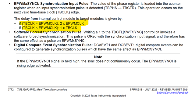
    There is a note in TRM that says synchronization may take 1~2 TBCLK. So if you zoom in the rising edge of master and slave ePWM then you can see that difference. So generally we say add that static offset in TBPHS register and these edge will be perfectly aligned.

    Keeping this limitation in mind, one additional thing you can try with keeping all the suggested remedy above is that set global load sync event on period and not the zero. That way these registers will be ready in shadow register when TBCTR = ZERO and ready to load in active in one cycle all at once.

    This will avoid racing condition between synchronizing and global loading.

    Also, did you happen to evaluate or try the trip method I mentioned in thread above? Do you think that will work for you?

    Regards,

    Sumit

  • Sumit,

    I think you are correct in thinking the race condition is between the sync pulse and when TBCTR = 0, although I have global load sync event set to SYNCIN signal, not zero.  Thank you very much for looking into this.  I am considering how we want to change the PWMs by either altering the global load event or using the Trip Zone.

    Best,

    Will

  • Will, 

    Sure, please try either of these proposed method. Let me know if any doubts.

    Regards,

    Sumit