This thread has been locked.

If you have a related question, please click the "Ask a related question" button in the top right corner. The newly created question will be automatically linked to this question.

TMS320F28335: TMS320F28335 solder ball issue

Part Number: TMS320F28335

Hello,

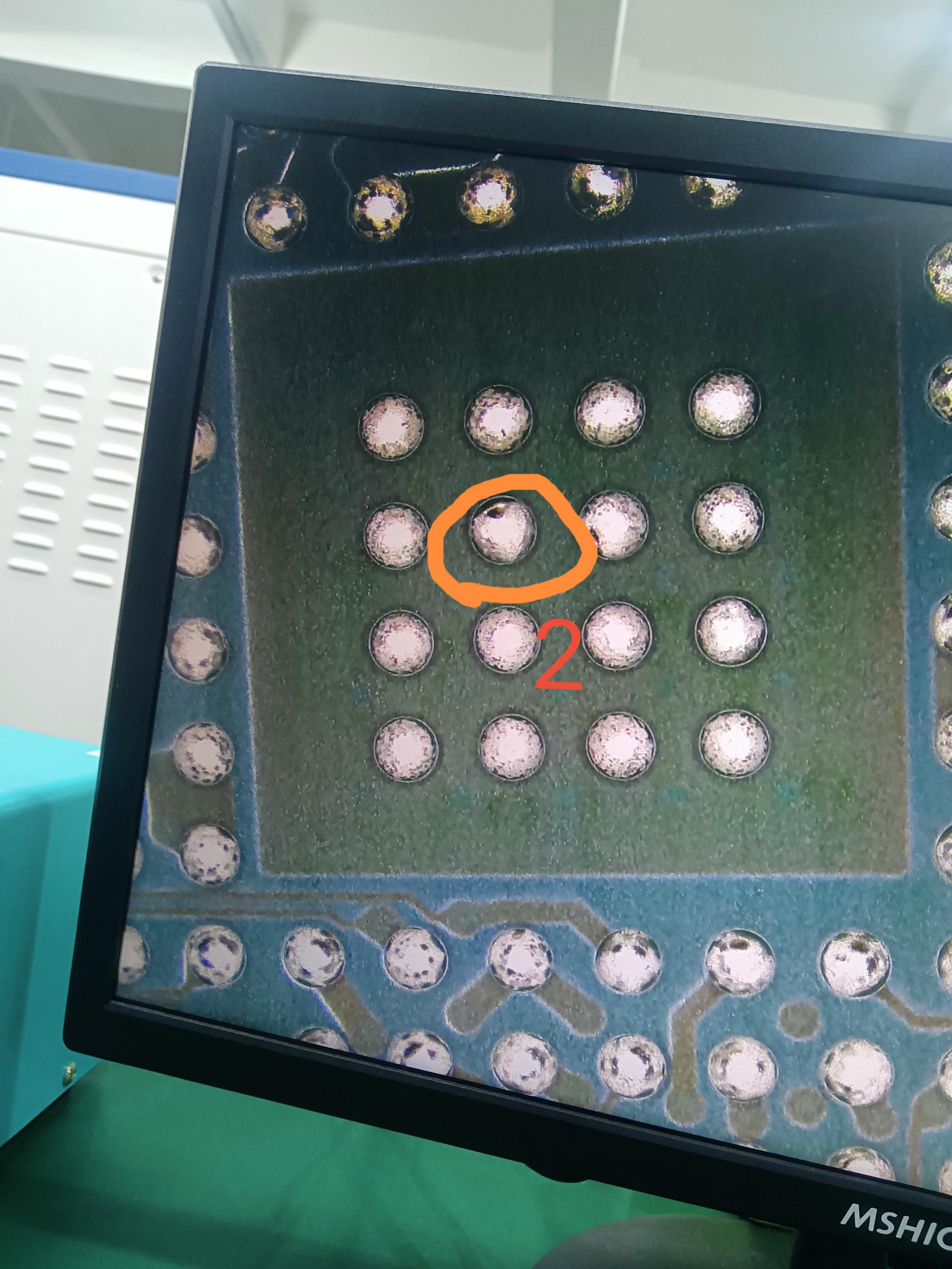
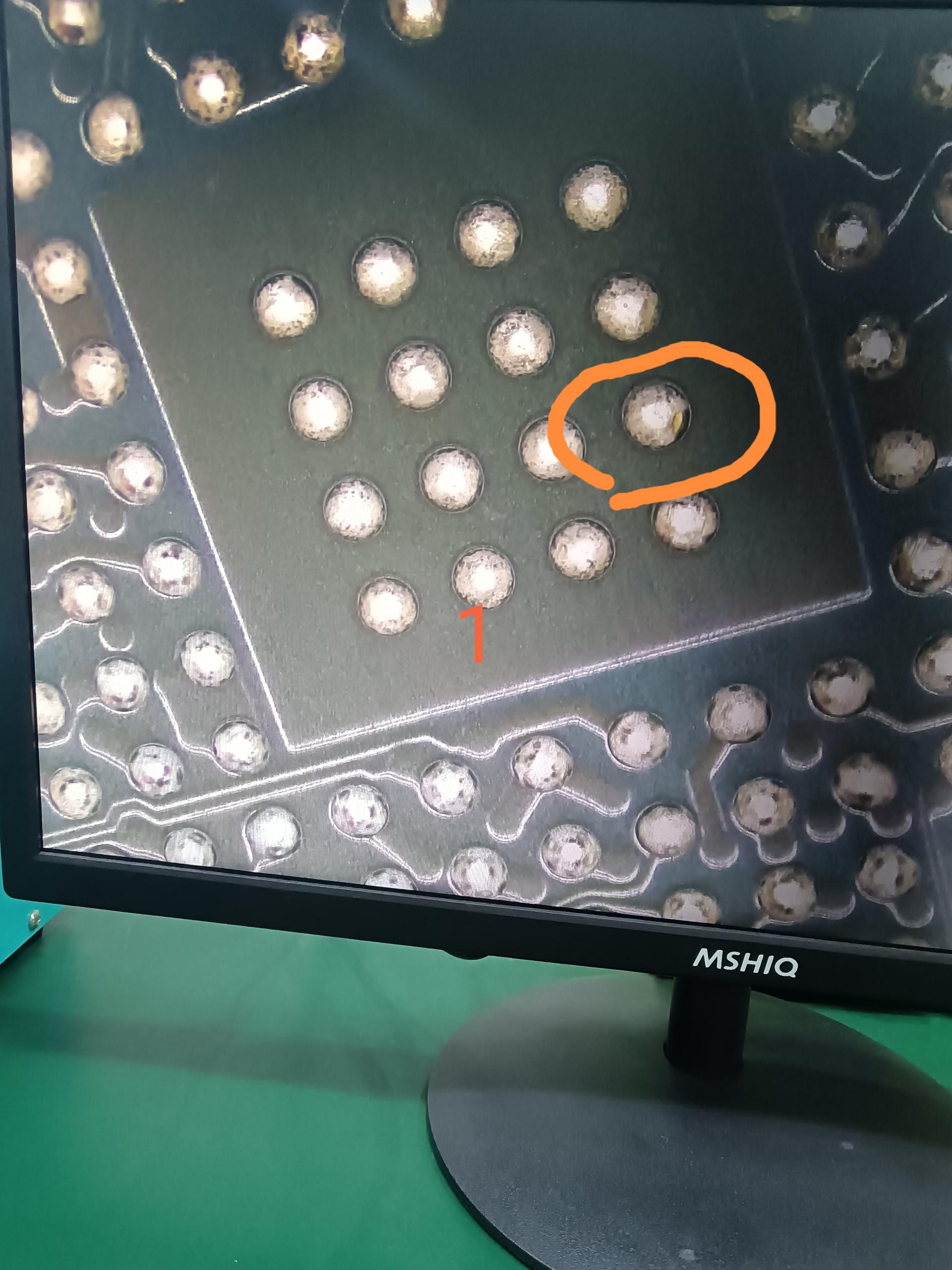
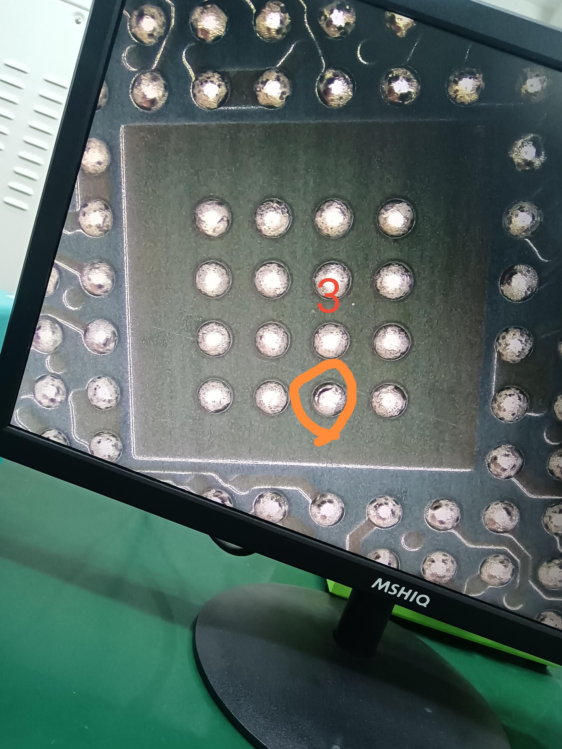
The TMS320F28335 chip solder ball has the following issues, resulting in virtual soldering during soldering. Please help to check if there are any changes to the welding process and conditions. It can avoid the problem of virtual soldering. Thanks.

  1. Some solder balls appear to be partially missing.image_1778678220979.jpgimage_1778678304381.jpgimage_1778678225208.jpgimage_1778678228562.jpg

2. The middle 16 pads are relatively smooth, while the surrounding pads are relatively rough.

image_1778678247389.jpg

  • Hi Jeno,

    Thank you for reaching out regarding the TMS320F28335 solder ball issues. The problems you're describing — partially missing solder balls and inconsistent pad surface finish (smooth center pads vs. rough outer pads) — are concerning quality issues that can lead to poor solder joints and reliability problems.


    1. Check Device Quality & Handling

    • Inspect incoming parts: Verify that the solder balls are intact upon receipt and document any issues before assembly.
    • Storage conditions: Ensure proper moisture sensitivity level (MSL) handling. The TMS320F28335 should be stored and handled according to J-STD-020 standards .
    • Check for physical damage: Missing solder balls could indicate mechanical damage during shipping or handling.

    2. Pad Surface Finish Concerns

    The difference in pad surface finish (smooth center vs. rough outer pads) may suggest:

    • Possible oxidation on outer pads
    • Non-uniform solder mask application
    • PCB manufacturing quality issues
    • Different thermal exposure during previous processes

    3. Soldering Process Optimization

    For BGA packages like the TMS320F28335, consider the following process adjustments:

    Solder Paste Application:

    • Use Type 3 or Type 4 solder paste for better print definition
    • Ensure proper stencil thickness (typically 0.125 mm for BGA)
    • Verify paste volume is adequate but not excessive

    Reflow Profile:

    • Follow the temperature profile specified in the TMS320F28335 datasheet
    • Typical peak temperature: 235–245°C for SAC305 solder
    • Time above liquidus: 60–90 seconds
    • Ramp rates: 2–3°C/second

    PCB Pad Design:

    • Verify NSMD (Non-Solder Mask Defined) pad design
    • Pad diameter should be 80–90% of solder ball diameter
    • Ensure proper solder mask clearance

    Additional Resources:

    Best Regards,

    Zackary Fleenor

  • Hi Jeno,

    I wanted to follow up on the solder ball quality issues you reported with the TMS320F28335. I hope the recommendations I provided have been helpful in addressing the virtual soldering problems.

    Have you had a chance to:

    • Inspect incoming parts to verify solder ball integrity before assembly?
    • Review your reflow profile against the datasheet specifications?
    • Check the PCB pad design and surface finish consistency?

    I'm curious to know if you've made any progress or if you're still experiencing these issues. If you've implemented any of the suggested process changes, I'd be interested to hear about your results.

    If you're still encountering problems, please let me know:

    • Whether the issues persist with multiple lots/date codes of the device
    • Your current reflow profile parameters (peak temp, time above liquidus, ramp rates)
    • Any X-ray or cross-section analysis results if available
    • The PCB pad finish type (ENIG, OSP, etc.)

    This additional information would help me provide more targeted guidance or escalate to our quality/package engineering teams if needed.

    Looking forward to hearing from you!

    Best Regards,

    Zackary Fleenor