Part Number: TMS320F28388D
Hello,
I'm tryting setting CLB TILES as the ECAP function.
I've refered and followed the example provided by TI, and been making my own PJT.
- Input signal matching: Real external pulse signal -> GPIO5 -> INPUTXBAR7 -> AUXSIG0 -> CLB XBAR MUX17 -> CLB1_BASE CLB_IN0/1/2
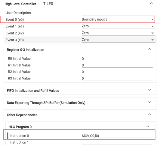
- Configurate the TILE0 like the below
//---------------------------------------------------------------------------
// TILE0
//---------------------------------------------------------------------------
#define TILE0_PIPELINE_MODE 0
#define TILE0_CFG_OUTLUT_0 0x0
#define TILE0_CFG_OUTLUT_1 0x0
#define TILE0_CFG_OUTLUT_2 0x0
#define TILE0_CFG_OUTLUT_3 0x0
#define TILE0_CFG_OUTLUT_4 0x0
#define TILE0_CFG_OUTLUT_5 0x0
#define TILE0_CFG_OUTLUT_6 0x0
#define TILE0_CFG_OUTLUT_7 0x0
#define TILE0_CFG_LUT4_IN0 0x1498
#define TILE0_CFG_LUT4_IN1 0x6b40
#define TILE0_CFG_LUT4_IN2 0x0
#define TILE0_CFG_LUT4_IN3 0x0
#define TILE0_CFG_LUT4_FN10 ((0x88880000) | 0x5555)
#define TILE0_CFG_LUT4_FN2 0x8888
#define TILE0_CFG_FSM_EXT_IN0 0x19
#define TILE0_CFG_FSM_EXT_IN1 0x0
#define TILE0_CFG_FSM_EXTRA_IN0 0x0
#define TILE0_CFG_FSM_EXTRA_IN1 0x0
#define TILE0_CFG_FSM_NEXT_STATE_0 ((0xa5a50000) | 0x5a5a)
#define TILE0_CFG_FSM_NEXT_STATE_1 ((0x00000) | 0x0)
#define TILE0_CFG_FSM_NEXT_STATE_2 ((0x00000) | 0x0)
#define TILE0_CFG_FSM_LUT_FN10 ((0x00000) | 0xaaaa)
#define TILE0_CFG_FSM_LUT_FN2 0x0
#define TILE0_FSM_MISC_CONTROL 0x0
#define TILE0_CFG_COUNTER_RESET 0x359
#define TILE0_CFG_COUNTER_EVENT 0x0
#define TILE0_CFG_COUNTER_MODE_0 0xf8
#define TILE0_CFG_COUNTER_MODE_1 0x108
#define TILE0_CFG_TAP_SEL 0x0
#define TILE0_CFG_MISC_CONTROL (0x0 | TILE0_FSM_MISC_CONTROL)
#define TILE0_COUNTER_0_MATCH1_VAL 0
#define TILE0_COUNTER_0_MATCH2_VAL 0
#define TILE0_COUNTER_0_LOAD_VAL 0
#define TILE0_COUNTER_1_MATCH1_VAL 0
#define TILE0_COUNTER_1_MATCH2_VAL 0
#define TILE0_COUNTER_1_LOAD_VAL 0
#define TILE0_COUNTER_2_MATCH1_VAL 0
#define TILE0_COUNTER_2_MATCH2_VAL 0
#define TILE0_COUNTER_2_LOAD_VAL 0
#define TILE0_SPI_EN 0
#define TILE0_HLC_EVENT_SEL 0x5f2f
#define TILE0_HLC_R0_INIT 0
#define TILE0_HLC_R1_INIT 0
#define TILE0_HLC_R2_INIT 0
#define TILE0_HLC_R3_INIT 0
void initTILE0(uint32_t base)
{
uint16_t i;
//
// Pipeline Mode
//
CLB_disablePipelineMode(base);
//
// Output LUT
//
CLB_configOutputLUT(base, CLB_OUT0, TILE0_CFG_OUTLUT_0);
CLB_configOutputLUT(base, CLB_OUT1, TILE0_CFG_OUTLUT_1);
CLB_configOutputLUT(base, CLB_OUT2, TILE0_CFG_OUTLUT_2);
CLB_configOutputLUT(base, CLB_OUT3, TILE0_CFG_OUTLUT_3);
CLB_configOutputLUT(base, CLB_OUT4, TILE0_CFG_OUTLUT_4);
CLB_configOutputLUT(base, CLB_OUT5, TILE0_CFG_OUTLUT_5);
CLB_configOutputLUT(base, CLB_OUT6, TILE0_CFG_OUTLUT_6);
CLB_configOutputLUT(base, CLB_OUT7, TILE0_CFG_OUTLUT_7);
//
// AOC
//
CLB_configAOC(base, CLB_AOC0, TILE0_OUTPUT_COND_CTR_0);
CLB_configAOC(base, CLB_AOC1, TILE0_OUTPUT_COND_CTR_1);
CLB_configAOC(base, CLB_AOC2, TILE0_OUTPUT_COND_CTR_2);
CLB_configAOC(base, CLB_AOC3, TILE0_OUTPUT_COND_CTR_3);
CLB_configAOC(base, CLB_AOC4, TILE0_OUTPUT_COND_CTR_4);
CLB_configAOC(base, CLB_AOC5, TILE0_OUTPUT_COND_CTR_5);
CLB_configAOC(base, CLB_AOC6, TILE0_OUTPUT_COND_CTR_6);
CLB_configAOC(base, CLB_AOC7, TILE0_OUTPUT_COND_CTR_7);
//
// LUT 0 - 2 are configured as macros in clb_config.h; these macros are used in
// CLB_selectLUT4Inputs and CLB_configLUT4Function
//
//
// Equation for Look-Up Table Block 0 for TILE0: !i0
//
// Equation for Look-Up Table Block 1 for TILE0: i0&i1
//
// Equation for Look-Up Table Block 2 for TILE0: i0&i1
//
// LUT Configuration
//
CLB_selectLUT4Inputs(base, TILE0_CFG_LUT4_IN0, TILE0_CFG_LUT4_IN1, TILE0_CFG_LUT4_IN2, TILE0_CFG_LUT4_IN3);
CLB_configLUT4Function(base, TILE0_CFG_LUT4_FN10, TILE0_CFG_LUT4_FN2);
//
// FSM 0 - 2 are configured in <file>
//
//
// Output equation for Finite State Machine 0 for TILE0: s0
// State 0 output equation for Finite State Machine 0 for TILE0: s0^e0
// State 1 output equation for Finite State Machine 0 for TILE0: !(s0^e0)
//
//
// FSM
//
CLB_selectFSMInputs(base, TILE0_CFG_FSM_EXT_IN0, TILE0_CFG_FSM_EXT_IN1, TILE0_CFG_FSM_EXTRA_IN0, TILE0_CFG_FSM_EXTRA_IN1);
CLB_configFSMNextState(base, TILE0_CFG_FSM_NEXT_STATE_0, TILE0_CFG_FSM_NEXT_STATE_1, TILE0_CFG_FSM_NEXT_STATE_2);
CLB_configFSMLUTFunction(base, TILE0_CFG_FSM_LUT_FN10, TILE0_CFG_FSM_LUT_FN2);
//
// Counter 0 - 2 are configured in <file>
//
//
// Counters
//
CLB_selectCounterInputs(base, TILE0_CFG_COUNTER_RESET, TILE0_CFG_COUNTER_EVENT, TILE0_CFG_COUNTER_MODE_0, TILE0_CFG_COUNTER_MODE_1);
CLB_configMiscCtrlModes(base, TILE0_CFG_MISC_CONTROL);
CLB_configCounterLoadMatch(base, CLB_CTR0, TILE0_COUNTER_0_LOAD_VAL, TILE0_COUNTER_0_MATCH1_VAL, TILE0_COUNTER_0_MATCH2_VAL);
CLB_configCounterLoadMatch(base, CLB_CTR1, TILE0_COUNTER_1_LOAD_VAL, TILE0_COUNTER_1_MATCH1_VAL, TILE0_COUNTER_1_MATCH2_VAL);
CLB_configCounterLoadMatch(base, CLB_CTR2, TILE0_COUNTER_2_LOAD_VAL, TILE0_COUNTER_2_MATCH1_VAL, TILE0_COUNTER_2_MATCH2_VAL);
CLB_configCounterTapSelects(base, TILE0_CFG_TAP_SEL);
//
// HLC is configured in <file>
//
//
// HLC
//
CLB_configHLCEventSelect(base, TILE0_HLC_EVENT_SEL);
CLB_setHLCRegisters(base, TILE0_HLC_R0_INIT, TILE0_HLC_R1_INIT, TILE0_HLC_R2_INIT, TILE0_HLC_R3_INIT);
for(i = 0; i <= CLB_NUM_HLC_INSTR; i++)
{
CLB_programHLCInstruction(base, i, TILE0HLCInstr[i]);
}
}
However, the counters do not work properly and need helps to improve it.
If anyone can review it, please give me feedback.
Best regards,