TMS320F28035: Issue with MCU Reset After Power Cycle in TMS320F28035

Part Number: TMS320F28035
Other Parts Discussed in Thread: C2000WARE, LP-XDS110ET

Hi TI Team,

I am facing an issue with the TMS320F28035 MCU after flashing the firmware.

Currently, I am flashing the MCU through JTAG. During debugging and immediately after flashing, the MCU works properly. However, after performing a power reset, the MCU is not responding and no operation is being executed.

It appears that the MCU is not booting correctly after a power cycle. Kindly help me resolve this issue as soon as possible.

Thanks and Regards 

Shahajahan

  • Shahajahan,

    This is typically caused by an incorrect/non-existent boot vector in the base project.

    Please take a look at this example in C2000Ware C:\ti\c2000\C2000Ware_26_01_00_00\device_support\f2803x\examples\c28\flash_f28035

    I would compare the .cmd file and main.c against your own.  Also note the inclusion of code_start_branch.asm file that gets called first.  There is also memcopy function call that is required if you have code that is relocated to RAM at run time.

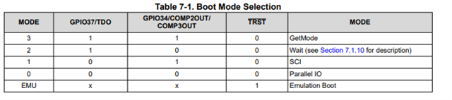
    Another common issue is that the boot pins are not correctly set to enable flash boot; you'll want to make sure these are pulled high for flash boot.

    Finally, for debug purposes, we have an EMUBOOT option, that when the debugger is connected a location in RAM is read vs boot pins to determine boot mode.  There should be a script for this in CCS menu; essentially you would load your code, perform a device Reset via CCS, then Set EMUBOOT for flash and run.  If this fails then it means a standalone boot will not work; and we have to resolve those issues.

    Best,

    Matthew

  • Hi Matthewpate,

    Still i a,m facing an issue after power reset it is not working 

  • Hi Shahajahan,

    Matthew is currently out of office, please expect a delayed response.

    Best Regards,

    Delaney

  • Hi Delaney,

    Could you kindly help me resolve this issue?

    Thank you

    Shahajahan

  • Hi Shahajahan,

    Matthew is the expert on this topic so he is the right person to help. He should be back soon and have a response in 1-2 days.

    Best Regards,

    Delaney 

  • Shahajahan,

    If you have compared the resources(.cmd file, memcopy usage on main.c, etc) and see no differences then I'm not sure what could be incorrect.  Did you try to load the flash_28035 project and observe if it works as intended in standalone boot mode?

    One other idea would be use use our emulation boot feature to mimic what a flash boot would look like if the emulator is not connected.

    To do this:

    1)Connect to the device with JTAG and launch Code Composer

    2)Load your ,out file via CCS.

    2a)Set a breakpoint near the beginning of you code

    3)Under the "Run" tab in the toolbar select Reset ->CPU Reset

    4)Under the "Scripts: tab go to Emu Boot Mode Select ->EMUFLASHBOOT

    5)Then run the device(play button).

    This will mimic a XRSn based startup, going through the BROM and ultimately your source code.  You should see the CCS hit your breakpoint to know that everything worked correctly.

    If this works, it means that your boot pins are not set correctly per my last post.  If this doesn't work, it likely means that you haven't added the code_start_branch.asm, or placed your code correctly via the linker.

    You can try this with the example I mentioned above, it should work out of the box correctly.

    Best,

    Matthew

  • Hi Matthew Pate,

    The board is working now; however, I am encountering an issue with the TRSTn pin configuration. For normal operation after flashing, TRSTn is pulled down with a 2.2 kΩ resistor. During the flashing process, TRSTn must be pulled up to 3.3 V through a 10 kΩ resistor, and R17 needs to be removed.

    Please see the attached schematic for reference.

    Thanks & Regards

    Shahajahan

  • Hi Matthew ,

    I am using LP-XDS110ET For flashing

  • Shahajahan,

    As you have noted, the LP-XDS110ET does not have a native TRSTn signal to connect to our F28035. 

    The 2.2kPD is recommended for production/deployment to prevent the JTAG tap from accidentally getting pulled out of reset by noise or environmental factors.  However, to connect to the F28035 thru JTAG you will need to pull this pin high before the JTAG connection sequence on TMS/TCK/TDI begin.  

    A few options;

    1)The https://www.ti.com/tool/TMDSEMU110-U does support TRSTn signal, and can overdrive the 2.2kPD to connect automatically

    2)If you want to use the LP-XDS110ET, then you will need to pull TRSTn high manually, but only when you want to connect.  In this sense a static resistor is not going to be the best option(plus 10kOhm is too weak to overdrive the 2.2kOhm PD).  You could either wire up a switch to tie TRSTn to 3.3V directly and flip it when you have JTAG header and are ready to connect...or perhaps a wire lead that you could jumper to 3.3V signal on your board when you want to connect.

    For development, you can back off the 2.2kOhm, PD, so that you can use a smaller pullup, maybe switch to use a 10kPD and then a 2.2kPU with the method detailed in #2 above.

    Best,

    Matthew