This thread has been locked.

If you have a related question, please click the "Ask a related question" button in the top right corner. The newly created question will be automatically linked to this question.

TMS320F280025: The ADC issue for TMS320F280025

Part Number: TMS320F280025

Hi

We use the F280025 in our solar inverter project ,and now, we have below issue for the ADC:

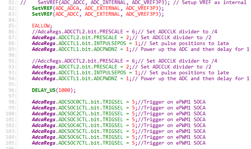
  1. Our ADC initial configuration: 

image.png

            The initial pin configuration:

image.png

Our issue is: a. The power is less than 2KW, read the register of A1=1550, it is consistent with input;

                     b. The power is more than 2KW, the voltage of the A1=1.2V, and read the register of A1=59

                     c. We change the adccRegs. ADCSOC0CTL. bit. ACQPS to 18, the A1 is normal, But as the power 

                         increases, the ADC result registers of A0=2000 and A8=1200;

    2. We Change the channel of the ADC will cause interference and actual inconsistency in the sampling of

        other channels:

       a. A9 sampling decreases as the power increases. At the same time, the sampling results of the two channels

           of A1 are also different;
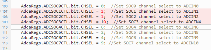
       image.png

      b. We change the below ADC configuration and the A9 and A0 sampling is normal:
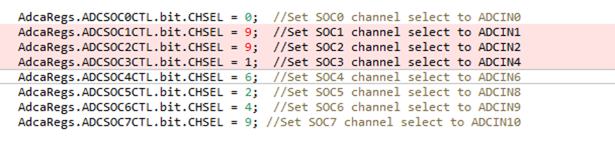
      image.png

     c. Please advise that why this ADC need to set as above?

    3. We change the adccRegs. ADCSOC0CTL. bit. ACQPS from 18 to 30, the result is also abnormal;

    4. Plesae kindly check the below schematic diagram and our ADC configuration, and provide your comment that 

        how to solve this issue, thanks.
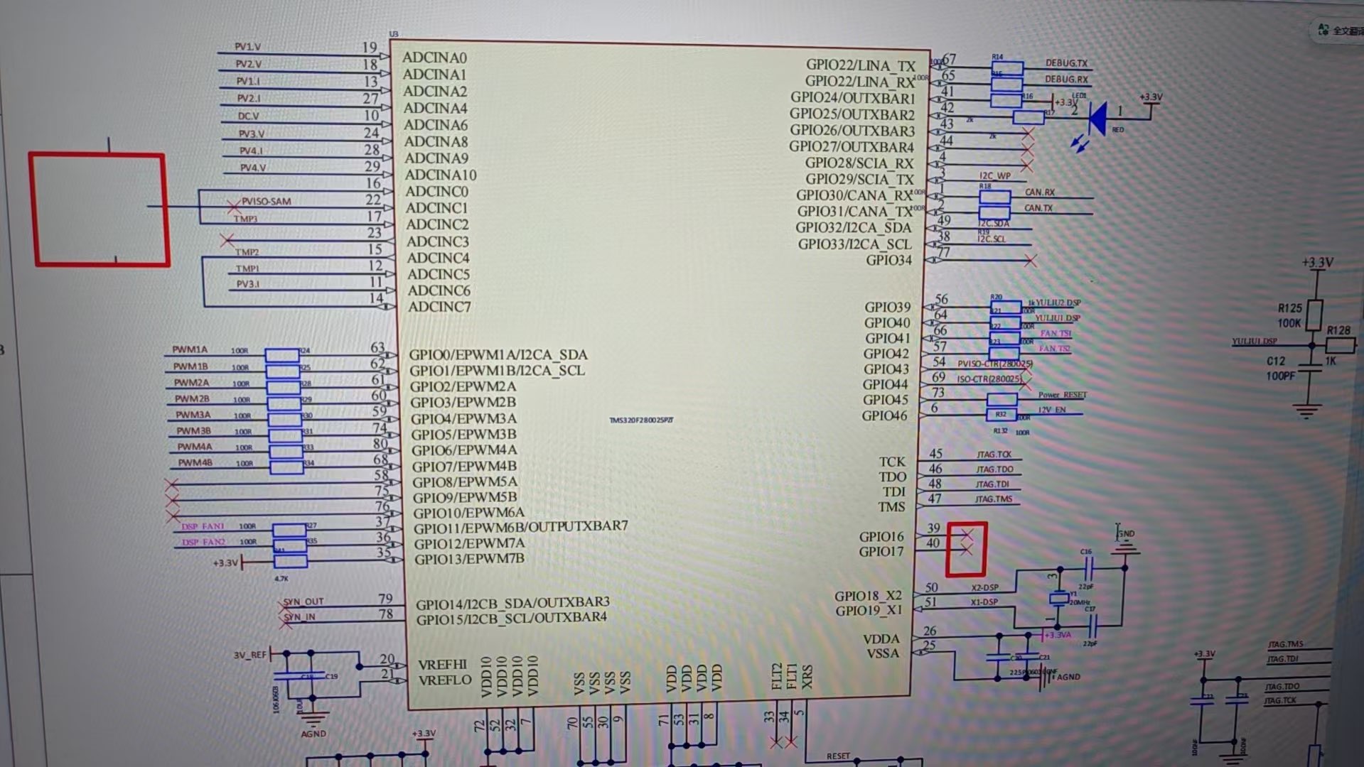
5412ae4ec795045bca6dbae9ce5af2f3.jpg


  • Hello Zhang,

    1. This will most likely be caused by the ADC's sample window being too short. Per the TMS320F28002x datasheet, minimum ADC Sample window duration (Table 6.12.3.2.1) is 75ns. An ACQPS value of 6 SYSCLK periods (+ 1 per Section 15.12 in the Tech Reference Manual), is 70ns at the highest clocking speed (as correctly calculated in the screenshot you shared). This violates the sample window minimum. An ACQPS value of 7 or more will solve this issue.

    c. I am unable to diagnose the issue with the given info. Please include expected value(s), expected voltage(s) at the ADC's input, and/or scope shots of the voltage(s) at the ADC's input.

    2. Could you clarify the issue you are seeing here? FYI, it is known that high dV/dt signals (such as digital signals) connected to AIO can cause cross-talk with adjacent analog signals (mentioned throughout the TRM). Please include expected value(s), expected voltage(s) at the ADC's input, and/or scope shots of the voltage(s) at the ADC's input.

    3. Could you clarify what abnormality you are seeing with ACQPS changing from 18 to 30? Ideally, include the changes in values seen against expected values. Please keep in mind that there is an ideal settling time depending on your external circuitry (see TRM Section 15.13.2 for the equation).

    Best,

    Ryan

  • Hello, Zhang.

    I wanted to follow up and see if you had any additional feedback/questions on this topic? If my previous reply solved your ADC issues, do let us know!

    Best,

    Ryan

  • Hi Ryan,

    The customer is still testing the board now.

    For your reply itme#3, customer feedback that ACQPS to 30 will affects sampling for PV1 and PV3;

    The ACQPS set to 18, the input voltage is 36V, the PV1 and PV3 is 35.9V, the PV2 is 0V,

    If ACQPS set to 30, the PV1 is 42V, the PV2 is 36V, the PV3 is 24V, thanks.