TMS320F28388D: SCI Response Drops Stop Bit

Part Number: TMS320F28388D
Other Parts Discussed in Thread: SYSCONFIG, C2000WARE

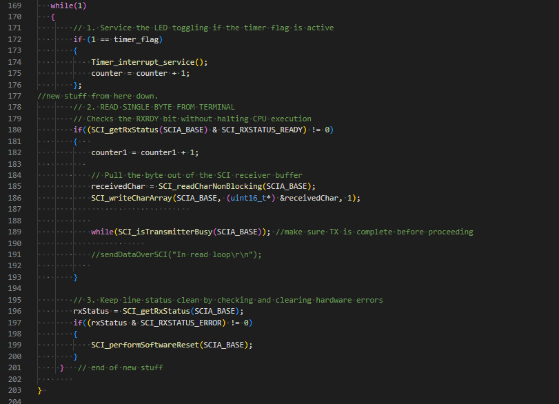
I am bringing up a board with an TMS320F28388D part using an FTDI chip to talk to SCIA (pins GPIO8 and GPIO9).  The following code is supposd to read a character and send it back to to the terminal (9600 baud, 8, N, 1).

image.png

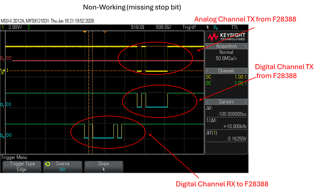
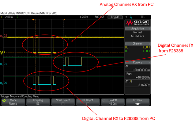
When I send a series of a single character (for example 'k'), the return is corrupted about 30% of the time (see below).

image.png

I monitored the GPIO9/19 from the TMS320F28388D and noticed that the stop bit is getting dropped leading to the issue.  Otherwise, the signals are clean and have the right timing and amplitude.  It is just the stop-bit that leads to the corruption.

I consulted the forum and was advised to add the following line:

while(SCI_isTransmitterBusy(SCIA_BASE)); 
 
However, this did not change the result.  Any other suggestions would be greatly appreciated.


  • Hi Kent,

    Which LSPCLK frequency do you have configured? There may be some associated error with the 9600 baud rate and LSPCLK combination.

    Also, in the errored cases, do you see the received character read in correctly if you watch the receivedChar variable in CCS?

    Best Regards,

    Delaney

  • Here is how I have the SCI module configured:

    I am using DEVICE_LSPCLK_FREQ to configure the SCI module.  

    When the device works correctly, "receivedChar" returns the correct ascii hex value.  When it fails, it is incorrect.  For example, I sent 'A' and received a 0x41.  However, when it failed it returned 0xC2.  Similarly, when I send 'B', I get a 0x42 when it works but I get a 0xC3 when it is corrupted.  I observed the same behavior at other baud rates as well.

  • Hi Kent,

    I see, so the issue is really on the RX side. Are any SCIRXST register flags getting set when the issue is present? (Can you open the register's view in CCS with continuous refresh toggled on and see what the register is set to?). 

    Best Regards,

    Delaney

  • Delaney,

    When the issue is not present the registers for an 'A' report the following:

    When the issue is present, the registers report (again I am typing an 'A'):

    Thanks,

    Kent

  • Hi Kent,

    I believe default DEVICE_LSPCLK_FREQ is 50MHz since SYSCLK/4 is the default setting. If that is the case, the known error is very minimal (~0.01%).

    Are you scoping the signal being received on the F2838x directly? Is this signal missing the stop bit? Do you see any difference between the correctly received signal and the incorrectly received signal?

    Best Regards,

    Delaney

  • Delaney,

    Here is a .bmp of the scope trace for a working 'A':

    The trace D0 is the input (RX) from the PC to the chip on GPIO9, D1 is the output trace (TX) from the chip to the PC on GPIO8.  The yellow trace is an analog channel connected to GPIO8 to look for noise.  Below is a similar trace for when it fails showing the missing stop-bit for a non-working 'A':

    The stop bit is there from the PC in both cases, but in the non-working case, the stop bit is not sent by the chip back to the PC.  

    I checked the sysconfig to verify that LSPCLK is 50MHz and it appears to be set correctly.

    Thanks,

    Kent

  • Hi Kent,

    Delaney is out of office until next week. In the meantime, I can try to make a suggestion.

    Can you try to reorder GPIO Init to come before the SCI init and double check your GPIO settings? You can follow the pattern from the reference examples in C2000Ware:  {C2000Ware}\driverlib\f2838x\examples\c28x\sci.

    e.g. all GPIO configuration moves before SCI_setConfig/SCI_enableModule, GPIO_setPinConfig (MUX to SCI function) and GPIO_setQualificationMode(ASYNC) present, TX pad type changed from PULLUP to STD (standard push-pull)

    I don't see the full GPIO init in the screen captures you sent so just want to rule this out.

    Best Regards,

    Allison

  • Allison,

    I checked the order and changed from pull-ups to push-pull.  However, there is no change in the behavior of the device.

    Here is the InitSCI function for the board.

    void initSCI(void)
    {
        // 1. Enable the SCI peripheral clock (example uses SCIA)
        SysCtl_enablePeripheral(SYSCTL_PERIPH_CLK_SCIA);
        SysCtl_enablePeripheral(SYSCTL_PERIPH_CLK_SCIB);
        SysCtl_enablePeripheral(SYSCTL_PERIPH_CLK_SCIC);
    
        // 2. Perform a software reset to clear any prior states
        SCI_performSoftwareReset(SCIA_BASE);
        SCI_performSoftwareReset(SCIB_BASE);
        SCI_performSoftwareReset(SCIC_BASE);
    
        // 3. Configure the SCI module 
        // Parameters: Base address, LSPCLK frequency, Baud Rate, Configuration flags
        SCI_setConfig(SCIA_BASE, 
                      DEVICE_LSPCLK_FREQ, 
                      9600, 
                      (SCI_CONFIG_WLEN_8 | SCI_CONFIG_PAR_NONE | SCI_CONFIG_STOP_ONE));
        SCI_setConfig(SCIB_BASE, 
                      DEVICE_LSPCLK_FREQ, 
                      9600, 
                      (SCI_CONFIG_WLEN_8 | SCI_CONFIG_PAR_NONE | SCI_CONFIG_STOP_ONE));              
        SCI_setConfig(SCIC_BASE, 
                      DEVICE_LSPCLK_FREQ, 
                      9600, 
                      (SCI_CONFIG_WLEN_8 | SCI_CONFIG_PAR_NONE | SCI_CONFIG_STOP_ONE));              
    
        // 4. Initialize and clear FIFOs (Optional but recommended)
        SCI_resetChannels(SCIA_BASE);
        SCI_resetRxFIFO(SCIA_BASE);
        SCI_resetTxFIFO(SCIA_BASE);
        SCI_disableFIFO(SCIA_BASE);
    
        // 5. Enable the module
        SCI_enableModule(SCIA_BASE);
        SCI_enableTxModule(SCIA_BASE);
        SCI_enableRxModule(SCIA_BASE);
    
        SCI_resetChannels(SCIB_BASE);
        SCI_resetRxFIFO(SCIB_BASE);
        SCI_resetTxFIFO(SCIB_BASE);
        SCI_disableFIFO(SCIB_BASE);
    
        // 5. Enable the module
        SCI_enableModule(SCIB_BASE);
        SCI_enableTxModule(SCIB_BASE);
        SCI_enableRxModule(SCIB_BASE);
    
        SCI_resetChannels(SCIC_BASE);
        SCI_resetRxFIFO(SCIC_BASE);
        SCI_resetTxFIFO(SCIC_BASE);
        SCI_disableFIFO(SCIC_BASE);
    
        // 5. Enable the module
        SCI_enableModule(SCIC_BASE);
        SCI_enableTxModule(SCIC_BASE);
        SCI_enableRxModule(SCIC_BASE);
    
        // 6. Enable Pullups on GPIO8 and GPIO9
        GPIO_setPadConfig( GPIO_PIN_SCIA_RX, GPIO_PIN_TYPE_STD);
        GPIO_setPadConfig( GPIO_PIN_SCIA_TX, GPIO_PIN_TYPE_STD);
    
        // 6. Enable Pullups on GPIO11 and GPIO109
        GPIO_setPadConfig( GPIO_PIN_SCIB_RX, GPIO_PIN_TYPE_STD);
        GPIO_setPadConfig( GPIO_PIN_SCIB_TX, GPIO_PIN_TYPE_STD);
    
        // 6. Enable Pullups on GPIO13 and GPIO112
        GPIO_setPadConfig( GPIO_PIN_SCIC_RX, GPIO_PIN_TYPE_STD);
        GPIO_setPadConfig( GPIO_PIN_SCIC_TX, GPIO_PIN_TYPE_STD);
    
    }//initSCI
    

    Thanks,

    Kent

  • Hi Kent,

    Thanks for sharing the init. Please allow until Delaney's return later this week for a follow up.

    Best Regards,

    Allison

  • Hi Kent,

    Can you place the analog scope on the RX side instead? Based on the register values you showed before, the difference in transmit value makes sense according to what was being read in. The issue should be with the RX signal so I want to determine if there is any noise right at the input of the RX pin of the F2838x.

    Best Regards,

    Delaney

  • Delaney,

    Here is an analog scope trace of a working 'A' sent to the board:

    Here is the same setup with a non-working 'A'.

    The signals a not noisy from the PC to the F28388.

    Thanks,
    Kent