


Part Number: TMS320F28388D
Other Parts Discussed in Thread: SYSCONFIG
When I set up my clock tree for a 25MHz external oscillator and go into debug mode, the program hangs up on the following code:
#ifdef CPU1
//
// Verify the crystal frequency.
// Note: This check can be removed if you are not using XTAL as the PLL
// source
if( ((DEVICE_SETCLOCK_CFG & SYSCTL_OSCSRC_M) == SYSCTL_OSCSRC_XTAL) ||
((DEVICE_SETCLOCK_CFG & SYSCTL_OSCSRC_M) == SYSCTL_OSCSRC_XTAL_SE))
{
while(!Device_verifyXTAL(DEVICE_OSCSRC_FREQ / 1000000))
{
//
// The actual XTAL frequency does not match DEVICE_OSCSRC_FREQ!!
// Please check the XTAL frequency used.
//
// By default, the Device_init function assumes 25MHz XTAL.
// If a 20MHz crystal is used, please add a predefined symbol
// "USE_20MHZ_XTAL" in your CCS project.
// If a different XTAL is used, please update the DEVICE_SETCLOCK_CFG
// macro accordingly.
//
// Note that the latest F2838x controlCARDs (Rev.B and later) have been
// updated to use 25MHz XTAL by default. If you have an older 20MHz XTAL
// controlCARD (E1, E2, or Rev.A), refer to the controlCARD
// documentation on steps to reconfigure the controlCARD from 20MHz to
// 25MHz.
//
DEVICE_DELAY_US(1000); // Note: oscillator can take up to
// 10ms to start up per data sheet
}
}
from the device.c file. I tried to comment out the code butit gets into another endless loop somewhere else in device_init(). My clock is a ASEGT-25.000mHZ-GC with the following waveform: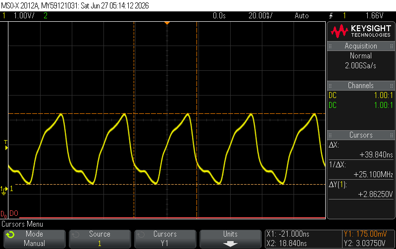
I am able to communicate at 9600 and 115200 baud on SCIA and the led timer interrupt works if I comment out the device_init(); however, I am having issues getting the DAC to work and the SPIA to work that I think are related to the device_init() problem. The board is set up to boot in parallel I/O (0x00). I am not sure that has anything to do with the problem. My main code is attached here:
//..........................Included Files...................................//
//
#include "driverlib.h"
#include "device.h"
#include "board.h"
#include <stdio.h>
#include <string.h>
#include <stdint.h>
//.............................Define Prototypes...........................//
void initSCI(void);
void sendDataOverSCIA(char *msg);
void sendDataOverSCIB(char *msg);
void sendDataOverSCIC(char *msg);
void Timer_interrupt_service(void);
void Flash_LED(uint32_t LED, uint8_t flashes);
void Write_to_SPIA(uint16_t TXdata);
//................................#defines...............................//
#define TRUE 1
#define BUFFER_SIZE 12
#define NCHARS 1024
//............................ Global variables............................//
int8_t timer_flag=0;
int8_t SCI_flag=0;
uint16_t receivedCharA;
uint16_t receivedCharB;
uint16_t receivedCharC;
uint16_t rxStatus;
char msg[] = "abcdefghijklmnopqrstuvwxyz\n\r";
char msg1[] = "XYZ";
char msg_C_B[] = "c";
char msg_B_C[] = "b";
uint16_t rxBuffer[10];
//......................................Interrupt Service.....................//
__interrupt void INT_Led_Toggle_Timer_ISR(void)
{
timer_flag = 1;
}//__interrupt void INT_Led_Toggle_Timer_ISR
//.................................. Main...................................//
//
void main(void)
{
// Device Initialization
SysCtl_disableWatchdog();
Device_init();
//
// Initializes Peripheral Interrupt Expansion module (PIE) and clears PIE registers. Disables CPU interrupts.
//
Interrupt_initModule();
Device_initGPIO();
//
// Initializes the PIE vector table with pointers to the shell Interrupt
// Service Routines (ISR).
//
Interrupt_initVectorTable();
Board_init();
initSCI();
//
// Enable Global Interrupt (INTM) and realtime interrupt (DBGM)
//
EINT;
ERTM;
//..................................Local Variables..........................//
uint32_t counter=0;
uint32_t counter1 = 0;
uint32_t counter2 = 0;
uint16_t index = 0;
char commandChar;
char commandCharC;
char tempChar[]="";
uint16_t txData = 0xA5A5;
uint16_t dacValueA = 0;
uint16_t dacValueB = 0;
uint16_t dacValueC = 0;
//.....................................Super Loop.............................//
while(TRUE)
{
// 1. Service the LED toggling if the timer flag is active
if (1 == timer_flag)
{
Timer_interrupt_service();
counter = counter + 1;
};
// 2. READ SINGLE BYTE FROM TERMINAL
// Checks the RXRDY bit without halting CPU execution
if((SCI_getRxStatus(SCIA_BASE) & SCI_RXSTATUS_READY) != 0)
{
counter1 = counter1 + 1;
// Pull the byte out of the SCI receiver buffer
receivedCharA = SCI_readCharNonBlocking(SCIA_BASE);
SCI_writeCharArray(SCIA_BASE, (uint16_t*) &receivedCharA, 1);
commandChar = (char) receivedCharA;
switch (commandChar)
{
case 'A':
// Code to execute if expression == 'A'
Flash_LED(GeoHT_LED8, 10);
sendDataOverSCIA("\r\nin A Loop\r\n");
sendDataOverSCIB(msg1);
sendDataOverSCIA("end of A loop\n\r");
break;
case 'B':
// Code to execute if expression == 'B'
Flash_LED(GeoHT_LED7, 10);
sendDataOverSCIA("\r\n");
for(counter=0; counter<NCHARS; counter++)
{
sendDataOverSCIC(msg_C_B);
GPIO_togglePin(GeoHT_LED6);
if((SCI_getRxStatus(SCIB_BASE) & SCI_RXSTATUS_READY) != 0)
{
counter1 = counter1 + 1;
// Pull the byte out of the SCI receiver buffer
//SCI_readCharArray(SCIC_BASE, rxBuffer, 10);
receivedCharB = SCI_readCharNonBlocking(SCIB_BASE);
SCI_writeCharArray(SCIA_BASE, (uint16_t*) &receivedCharB, 1);
}
}
sendDataOverSCIA("\r\n");
break;
case 'C':
// Code to execute if expression == 'C'
Flash_LED(GeoHT_LED6, 10);
sendDataOverSCIA("\r\n");
for(counter=0; counter<NCHARS; counter++)
{
sendDataOverSCIB(msg_B_C);
GPIO_togglePin(GeoHT_LED8);
if((SCI_getRxStatus(SCIC_BASE) & SCI_RXSTATUS_READY) != 0)
{
counter1 = counter1 + 1;
// Pull the byte out of the SCI receiver buffer
//SCI_readCharArray(SCIC_BASE, rxBuffer, 10);
receivedCharC = SCI_readCharNonBlocking(SCIC_BASE);
SCI_writeCharArray(SCIA_BASE, (uint16_t*) &receivedCharC, 1);
}
}
sendDataOverSCIA("\r\n");
break;
case 'D':
// Code to execute if expression == 'D'
Flash_LED(GeoHT_LED5, 10);
sendDataOverSCIA("D Loop\r\n");
//for (counter1=0; counter1<0xfff; counter1++)
while(1)
{
/*dacValueA = (uint16_t)((counter1) & 0xfff);
dacValueB = (uint16_t)((counter1) & 0xfff);
dacValueC= (uint16_t)((counter1) & 0xfff);
*/
DAC_setShadowValue(DACA_BASE, 0x7ff);
DAC_setShadowValue(DACB_BASE, 0x7ff);
DAC_setShadowValue(DACC_BASE, 0x7ff);
//DEVICE_DELAY_US(500);
//Flash_LED(GeoHT_LED5, 10);
}
break;
case 'E':
// Code to execute if expression == 'E'
Flash_LED(GeoHT_LED4, 10);
sendDataOverSCIA("E Loop\r\n");
break;
case 'F':
// Code to execute if expression == 'F'
Flash_LED(GeoHT_LED3, 10);
sendDataOverSCIA("F Loop\r\n");
break;
default:
// Code to execute if no cases match
break;//default
}
if((SCI_getRxStatus(SCIC_BASE) & SCI_RXSTATUS_READY) != 0)
{
counter1 = counter1 + 1;
// Pull the byte out of the SCI receiver buffer
//SCI_readCharArray(SCIC_BASE, rxBuffer, 10);
receivedCharC = SCI_readCharNonBlocking(SCIC_BASE);
SCI_writeCharArray(SCIA_BASE, (uint16_t*) &receivedCharC, 1);
}
while(SCI_isTransmitterBusy(SCIA_BASE)); //make sure TX is complete before proceeding
//sendDataOverSCI("In read loop\r\n");
}
// 3. Keep line status clean by checking and clearing hardware errors
rxStatus = SCI_getRxStatus(SCIA_BASE);
if((rxStatus & SCI_RXSTATUS_ERROR) != 0)
{
SCI_performSoftwareReset(SCIA_BASE);
counter2 = counter2 + 1;
}
}
}
//
// End of File
//
void initSCI(void)
{
// 1. Enable the SCI peripheral clock (example uses SCIA)
SysCtl_enablePeripheral(SYSCTL_PERIPH_CLK_SCIA);
SysCtl_enablePeripheral(SYSCTL_PERIPH_CLK_SCIB);
SysCtl_enablePeripheral(SYSCTL_PERIPH_CLK_SCIC);
// 2. Perform a software reset to clear any prior states
SCI_performSoftwareReset(SCIA_BASE);
SCI_performSoftwareReset(SCIB_BASE);
SCI_performSoftwareReset(SCIC_BASE);
// 3. Configure the SCI module
// Parameters: Base address, LSPCLK frequency, Baud Rate, Configuration flags
SCI_setConfig(SCIA_BASE,
DEVICE_LSPCLK_FREQ,
9600,
(SCI_CONFIG_WLEN_8 | SCI_CONFIG_PAR_NONE | SCI_CONFIG_STOP_ONE));
SCI_setConfig(SCIB_BASE,
DEVICE_LSPCLK_FREQ,
9600,
(SCI_CONFIG_WLEN_8 | SCI_CONFIG_PAR_NONE | SCI_CONFIG_STOP_ONE));
SCI_setConfig(SCIC_BASE,
DEVICE_LSPCLK_FREQ,
9600,
(SCI_CONFIG_WLEN_8 | SCI_CONFIG_PAR_NONE | SCI_CONFIG_STOP_ONE));
// 4. Initialize and clear FIFOs (Optional but recommended)
SCI_resetChannels(SCIA_BASE);
SCI_resetRxFIFO(SCIA_BASE);
SCI_resetTxFIFO(SCIA_BASE);
SCI_disableFIFO(SCIA_BASE);
// 5. Enable the module
SCI_enableModule(SCIA_BASE);
SCI_enableTxModule(SCIA_BASE);
SCI_enableRxModule(SCIA_BASE);
SCI_resetChannels(SCIB_BASE);
SCI_resetRxFIFO(SCIB_BASE);
SCI_resetTxFIFO(SCIB_BASE);
SCI_disableFIFO(SCIB_BASE);
// 5. Enable the module
SCI_enableModule(SCIB_BASE);
SCI_enableTxModule(SCIB_BASE);
SCI_enableRxModule(SCIB_BASE);
SCI_resetChannels(SCIC_BASE);
SCI_resetRxFIFO(SCIC_BASE);
SCI_resetTxFIFO(SCIC_BASE);
SCI_disableFIFO(SCIC_BASE);
// 5. Enable the module
SCI_enableModule(SCIC_BASE);
SCI_enableTxModule(SCIC_BASE);
SCI_enableRxModule(SCIC_BASE);
// 6. Enable Pullups on GPIO8 and GPIO9
GPIO_setPadConfig( GPIO_PIN_SCIA_RX, GPIO_PIN_TYPE_STD);
GPIO_setPadConfig( GPIO_PIN_SCIA_TX, GPIO_PIN_TYPE_STD);
// 6. Enable Pullups on GPIO11 and GPIO109
GPIO_setPadConfig( GPIO_PIN_SCIB_RX, GPIO_PIN_TYPE_STD);
GPIO_setPadConfig( GPIO_PIN_SCIB_TX, GPIO_PIN_TYPE_STD);
// 6. Enable Pullups on GPIO13 and GPIO112
GPIO_setPadConfig( GPIO_PIN_SCIC_RX, GPIO_PIN_TYPE_STD);
GPIO_setPadConfig( GPIO_PIN_SCIC_TX, GPIO_PIN_TYPE_STD);
}//initSCI
void sendDataOverSCIA(char *msg)
{
// Define the message to send
//const char *msg = "GeoHT F28388D Serial Port 1\n\r";
uint16_t msgLength = strlen(msg); // Length of the string
// SCI_writeCharArray requires a uint16_t* cast for the array
SCI_writeCharArray(SCIA_BASE, (uint16_t*)msg, msgLength);
// Optional (but recommended): wait for transmit FIFO to clear
// to prevent buffer corruption if sending multiple packets back-to-back.
while(SCI_isTransmitterBusy(SCIA_BASE));
}//sendDataOverSCIA
void sendDataOverSCIB(char *msg)
{
// Define the message to send
//const char *msg = "GeoHT F28388D Serial Port 1\n\r";
uint16_t msgLength = strlen(msg); // Length of the string
// SCI_writeCharArray requires a uint16_t* cast for the array
SCI_writeCharArray(SCIB_BASE, (uint16_t*)msg, msgLength);
// Optional (but recommended): wait for transmit FIFO to clear
// to prevent buffer corruption if sending multiple packets back-to-back.
while(SCI_isTransmitterBusy(SCIB_BASE));
}//sendDataOverSCIB
void sendDataOverSCIC(char *msg)
{
// Define the message to send
//const char *msg = "GeoHT F28388D Serial Port 1\n\r";
uint16_t msgLength = strlen(msg); // Length of the string
// SCI_writeCharArray requires a uint16_t* cast for the array
SCI_writeCharArray(SCIC_BASE, (uint16_t*)msg, msgLength);
// Optional (but recommended): wait for transmit FIFO to clear
// to prevent buffer corruption if sending multiple packets back-to-back.
while(SCI_isTransmitterBusy(SCIC_BASE));
}//sendDataOverSCIC
void Timer_interrupt_service(void)
{
GPIO_togglePin(GeoHT_LED3);
//GPIO_togglePin(GeoHT_LED4);
//GPIO_togglePin(GeoHT_LED5);
//GPIO_togglePin(GeoHT_LED6);
//GPIO_togglePin(GeoHT_LED7);
//GPIO_togglePin(GeoHT_LED8);
//sendDataOverSCI("GeoHT F28388D Serial Port 1\n\r");
//sendDataOverSCI("a\n\r");
timer_flag = 0;
}//Timer_interrupt_service
void Flash_LED(uint32_t LED, uint8_t flashes)
{
uint8_t counter=0;
for (counter=0; counter<flashes; counter++)
{
GPIO_togglePin(LED);
//DEVICE_DELAY_US(100000);//DEVICE_DELAY_US only works in RAM not in flash
}
}//Flash_LED
void Write_to_SPIA(uint16_t TXdata)
{
// Send a 16-bit word over SPIA
// Note: Ensure your character length is configured properly (e.g., 16-bit or 8-bit)
// This function will block until there is space in the SPI TX FIFO
SPI_writeDataBlockingFIFO(SPIA_BASE, TXdata);
}
The DAC is setup in sysconfig as shown:
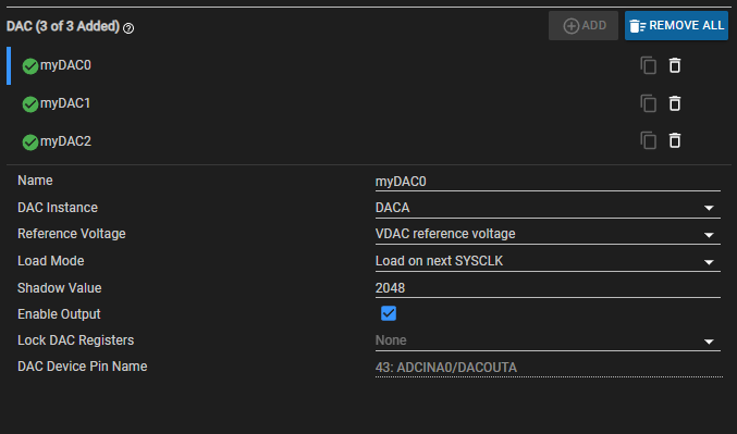
Any help would be greatly appreciated.
Thanks,
Kent
Kent
