This thread has been locked.

If you have a related question, please click the "Ask a related question" button in the top right corner. The newly created question will be automatically linked to this question.

TMS320F280039: The problem of period calculation in HRPWM

Part Number: TMS320F280039
Other Parts Discussed in Thread: TIDM-02013, , C2000WARE

Dear TI Expert,

When I was studying the source code of the TIDM-02013 project, I found the code related to the TBPRDHR register calculation in the following function quite confusing.

According to the content of the source program, the second parameter of the function is 500800 (the LLC resonant frequency), the third parameter is 120000000 (the system clock), and the macro TWO_RAISED_TO_THE_POWER_SIXTEEN is defined as 65536. In this case, the variable pwmPeriod_ticks will become a very large value. I would like to ask what is the reason for this calculation?

 Are there any easy-to-understand reference materials that introduce the content of HRPWM?

Looking forward to your reply, thank you!

Best Regards,

Power Wang
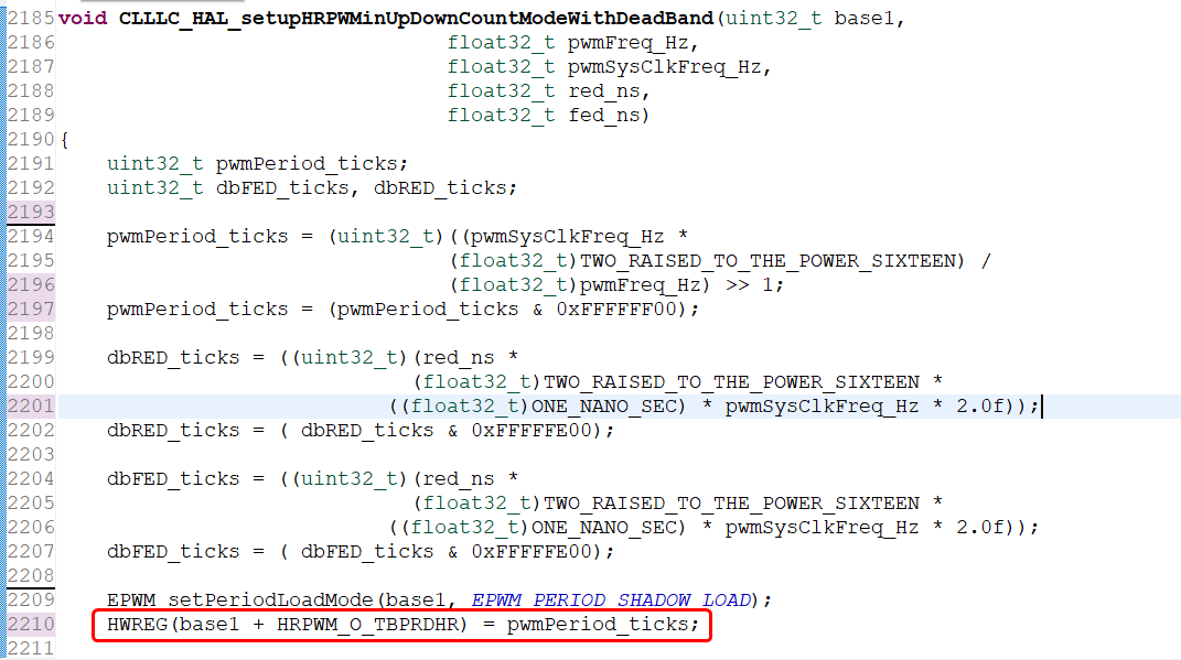
 

image.png

  • Hi Power,

    An EPWM expert will get back to you soon.

    Regards,
    Harisyam

  • Hi Power,

    TBPRDHR Calculation in TIDM-02013 Explained

    The large pwmPeriod_ticks value is intentional — it's a fixed-point arithmetic technique that packs both the integer period (TBPRD) and the fractional high-resolution period (TBPRDHR) into a single 32-bit value.

    How the Calculation Works

    From your screenshot of CLLLC_HAL_setupHRPWMinUpDownCountModeWithDeadBand, the formula is:

    pwmPeriod_ticks = (systemClock × 65536) / pwmFrequency / 2
    

    With your parameters (120 MHz clock, 500.8 kHz resonant frequency, up-down count mode):

    pwmPeriod_ticks = (120,000,000 × 65536) / 500,800 / 2 ≈ 7,864,729
    

    This result is a 32-bit fixed-point number where:

    • Upper 16 bits = integer period → loaded into TBPRD (the coarse clock ticks)
    • Lower 16 bits = fractional period → loaded into TBPRDHR (the high-resolution MEP steps)

    The division by 2 accounts for up-down count mode, where the PWM period equals 2×TBPRD 1.

    The code then masks with 0xFFFFFF00 and writes directly to the TBPRDHR address using HWREG, which simultaneously sets both TBPRD (upper 16 bits) and TBPRDHR (lower 16 bits, high byte) in one 32-bit write 1.

    Why Multiply by 65536?

    The multiplication by 2^16 shifts the integer portion into the upper half-word while preserving the fractional portion in the lower half-word. When auto-conversion is enabled (HRCNFG[AUTOCONV]=1), the hardware uses the HRMSTEP register (written by the SFO calibration function) to automatically scale the fractional value in TBPRDHR into the correct number of MEP steps (~150 ps resolution per step) 2.

    Recommended HRPWM Reference Materials

    1. TMS320F280039 Technical Reference Manual — HRPWM Section (Section 20.15): Covers MEP operation, register descriptions, and worked examples of TBPRDHR/CMPAHR calculations with auto-conversion 1

    2. SFO Library Documentation (Section 20.15.2): Explains the Scale Factor Optimizer calibration that keeps HRMSTEP updated at runtime 1

    3. C2000Ware SDK HRPWM Examples: The hrpwm_ex3_prd_updown_sfo.c example demonstrates high-resolution period control in up-down mode — directly relevant to your TIDM-02013 code 3

    4. E2E FAQ on ePWM/HRPWM: A curated list of common questions and answers 4

    Follow up: Are you planning to modify the resonant frequency dynamically at runtime, or are you primarily trying to understand the existing TIDM-02013 code before adapting it to your own CLLLC design?


    1. TMS320F280039 Technical Reference Manual - HRPWM
    2. TMS320F280039 Datasheet - HRPWM Electrical Data
    3. E2E: HRPWM Period Accuracy in Up Count Mode
    4. E2E FAQ: C2000 ePWM and HRPWM

    Thanks

    Srikanth

  • Hi Srikanth,

    Thank you very much for your detailed explanation.

    Best Regards,

    Power

  • Hi Srikanth,

    Thank you very much.

    Currently I'm primarily trying to understand the existing TIDM-02013 code before adapting it to my own CLLLC design.

    Do you have experimental boards available for purchase for TIDM-02013?

    Also, I think you are the EPWM expert mentioned earlier. I posted another thread about the drive waveforms in TIDM-02013, covering PFC, LLC and synchronous rectification. Could you please take a look at it when you are free and help me solve the related problems? The link to the post is as follows:

     RE: TMS320F280039C: PWM Waveforms of TIDM-02013  

    Best Regards.

    Power

  • Hi Power,

    TIDM-02013 boards are not available for purchase. You can use the design files available on ti.com to build. I will also check with the concerned expert to get back to your questions on TIDM-02013. You may also check with him if there are any boards available to lease it to you.

    Thanks

    Srikanth