


Part Number: TMS320F28379D
Hello team,
We are using TMS320F28379D and exploring to use UPP to drive a 8-bit parallel DAC at 25 MSPS instead of using GPIOs since this will save CPU time. The application requires very strict timing control when the transmission is started and stopped, i.e. it should be very deterministic. The transmission must always start on the same SYSCLK edge every single time. However, even though we are able to use UPP to drive the DAC at the required rate, there is a jitter where the first UPP CLK edge occurs. So, it is not deterministic and failing our purpose.
To test the jitter, inside a while(1) loop, I am making a GPIO high, starting the transmission, then after a delay of 1ms, making the GPIO low again. A part of the code is below:
....
So, the time duration between the GPIO going high and the first edge of any UPP Data pin (I used D0) should be always constant. But when observed in scope the UPP D0 pin edge keeps jittering left and right with respect to the GPIO edge. The jitter is more than 60ns which will kill our application. Our requirement is 0 ns i.e. always constant or no jitter. The yellow signal is the GPIO going HIGH and the blue signal is UPP D0. The actual jitter is more clearly visible in a video but here I attached just a snapshot. The cursors represents the extreme left and right of the jitter. Here, the first rising edge of the Blue signal alligns with the first cursor, but it keeps shifting and allign with the second cursor also. So, it randomly keeps jumping within the limits of the two cursors. But the duration between the two cursors is 61 ns, so the variation is 61ns.
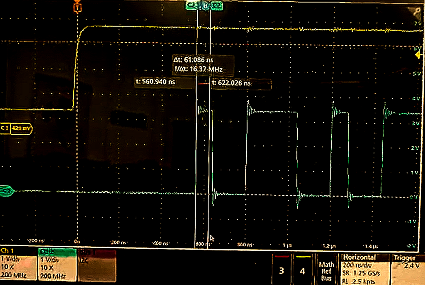
I also captured the UPP CLK signal instead of UPP D0 with the GPIO. The CLK always keeps coming as long as the device is ON. The rising edge of the UPP CLK never remains at constant duration from the GPIO edge.
I attached the source code which contains three files. Can you please help me in understanding what is causing the jitter and how to eliminate it?
Thank you,
Bhargav Saikia.

