


Hi,
I am using the McBSP in SPI mode, with my TMSF28335 for communicate with the DAC8568.
I have configured the McBSP for use the DSP as a Master and I send a package of 32bit.
This is the configuration:
void InitMcBSPa(void)
{
 McbspaRegs.SPCR2.all=0x0000; // Reset FS generator, sample rate generator & transmitter
 McbspaRegs.SPCR1.all=0x0000; // Reset Receiver, Right justify word, Digital loopback dis.
 McbspaRegs.PCR.all=0x0F08; // (CLKXM=CLKRM=FSXM=FSRM= 1, FSXP = 1)
 McbspaRegs.SPCR1.bit.DLB = 1;
 McbspaRegs.SPCR1.bit.CLKSTP = 2;
 McbspaRegs.PCR.bit.CLKXP = 1; // IF 0 Transmit data is sampled on the rising edge of CLKX.
 McbspaRegs.PCR.bit.CLKRP = 1; // IF 1 Receive data is sampled on the rising edge of MCLKR.
 McbspaRegs.RCR2.bit.RDATDLY = 1; // FSX setup time 1 in master mode. 0 for slave mode (Receive)
 McbspaRegs.XCR2.bit.XDATDLY = 1; // FSX setup time 1 in master mode. 0 for slave mode (Transmit)

 McbspaRegs.RCR1.bit.RWDLEN1 = 0x5; // 32-bit word
 McbspaRegs.XCR1.bit.XWDLEN1 = 0x5; // 32-bit word

 McbspaRegs.SRGR2.all = 0x2000; // CLKSM=1, FPER = 1 CLKG periods
 McbspaRegs.SRGR1.bit.FWID = 0; // Frame Width = 1 CLKG period
 McbspaRegs.SRGR1.bit.CLKGDV = 99; // CLKG frequency = LSPCLK/(CLKGDV+1) = 30MHz / 100 = 300kHz

 McbspaRegs.SPCR2.bit.GRST = 1; // Enable the sample rate generator
 delay_loop(100); // Wait at least 2 SRG clock cycles
 McbspaRegs.SPCR2.bit.XRST = 1; // Release TX from Reset
 McbspaRegs.SPCR1.bit.RRST = 1; // Release RX from Reset
 McbspaRegs.SPCR2.bit.FRST = 1; // Frame Sync Generator reset
}
void InitMcBSPaGpio(void)
{
 EALLOW;
 // Configure McBSPa as SPI

 EALLOW;
 GpioCtrlRegs.GPAMUX2.bit.GPIO20 = 2; // GPIO20 = MDXA (SPISIMO)
 GpioCtrlRegs.GPAMUX2.bit.GPIO21 = 2; // GPIO21 = MDRA (SPISOMI)
 GpioCtrlRegs.GPAMUX2.bit.GPIO22 = 2; // GPIO22 = MCLKXA (SPISIMO)
 GpioCtrlRegs.GPAMUX2.bit.GPIO23 = 2; // GPIO23 = MFSXA (SPISTE)


 GpioCtrlRegs.GPAPUD.bit.GPIO20 = 0; // Enable pull-up

 GpioCtrlRegs.GPAPUD.bit.GPIO21 = 0; // Enable pull-up
 GpioCtrlRegs.GPAQSEL2.bit.GPIO21 = 3; // Asynch input GPIO21 (MDRA)

 GpioCtrlRegs.GPAPUD.bit.GPIO22 = 0; // Enable pull-up
 GpioCtrlRegs.GPAQSEL2.bit.GPIO22 = 3; // Asynch input GPIO22 (MCLKXA)

 GpioCtrlRegs.GPAPUD.bit.GPIO23 = 0; // Enable pull-up


 EDIS;
}
For send data:
void send_DAC_McBSPa(Uint32 send_data){
// send 1 packages with McBSPa (in SPI mode)
while( McbspaRegs.SPCR2.bit.XRDY == 0 ) {} // wait for any previous SPI transactions to clear
McbspaRegs.DXR1.all = send_data;

}
I have tried to send instead 32 bit package, two 16 bit packages. But the MFSXA goes high between the two packages and the DAC lost the communication.
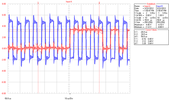
This is a screenshot of what I see with the scope, is a fragment of the 32bit package, the last 16 bit are always low. (the CLK has 32 edges, so the DAC
can read correctly the package, but the value of the package result wrong being the last 16 bit at 0)
Could someone help me please? Thank you!
