I'm going to try to illustrate this with actual code, but
will embed code fragments from 3 source files to pare the
size down to the minimum.
I am trying to get my first SPI driver working on a
TMS320F2812 using my own board. The 2812 is master and the
slave doesn't matter.
Inside main(), the first thing I do is call initSysCtrl():
>
> void main(void) {
> initSysCtrl();
>
which (among other things) calls initPeripheralClocks():
>
> initPeripheralClocks();
>
which (also among other things) configures the low-speed
peripheral clock and routes it to the SPI hardware.
>
> SysCtrlRegs.LOSPCP.all = 0x0002;
>
> SysCtrlRegs.PCLKCR.bit.SPIENCLK=1;
>
Function main() then calls my own function to initialize the
I/O ports:
>
> initIO();
>
inside which I configure the pins on port F to be driven by
the SPI hardware:
>
> EALLOW; /* Enable access to I/O cfg regs */
>
> /* + + + + + + + + + + + + + + + + + + + + + + + */
> /* GPIOF */
> /* - - - - - - - - - - - - - - - - - - - - - - - */
> /* P Gpio...Regs */
> /* e ----------- */
> /* r D P M D Q D */
> /* i i U U I U A */
> /* Port f r S Signal X R L T */
> /* ------- - - - ------------------ - - - - */
> /* 15 0 0 • 0 */
> /* GPIOF14 • I • --- unused --- 0 0 • 0 */
> /* GPIOF13 • O L selEEProm-L 0 1 • 0 */
> /* GPIOF12 • O L selPX2-L 0 1 • 0 */
> /* */
> /* GPIOF11 • O L selPX1-L 0 1 • 0 */
> /* GPIOF10 • I • mCUId2-H 0 0 • 0 */
> /* GPIOF9 • I • mCUId1-H 0 0 • 0 */
> /* GPIOF8 • I • mCUId0-H 0 0 • 0 */
> /* */
> /* GPIOF7 † I • canRx-H 1 0 • 0 */
> /* GPIOF6 † O L canTx-H 1 1 • 0 */
> /* GPIOF5 † I • diagTxDatBf-H 1 0 • 0 */
> /* GPIOF4 † O L diagRxDatBf-H 1 1 • 0 */
> /* */
> /* GPIOF3 • I • bootMode1-H 0 0 • 0 */
> /* GPIOF2 † O • spiClk-H 1 1 • 0 */
> /* GPIOF1 † O • spiMiso-H 1 1 • 0 */
> /* GPIOF0 † I • spiMosi-H 1 0 • 0 */
> /* - - - - */
> /* 0 3 • 0 */
> /* Hex 0 8 • 0 */
> /* values F 5 • 0 */
> /* 7 6 • 0 */
> /* + + + + + + + + + + + + + + + + + + + + + + + */
> GpioMuxRegs.GPFMUX.all = 0x00F7;
> GpioMuxRegs.GPFDIR.all = 0x3856;
> GpioDataRegs.GPFDAT.all = 0;
>
> EDIS; /* Disable access to I/O cfg regs */
>
I then go out and initialize the PIE vector table, which is
not relevant to this discussion and call initSPIFifo():
>
> initSPIFifo(); /* Initialize the Spi FIFO */
>
which I have tried to modify to disable the SPI FIFO:
>
> void initSPIFifo(void) {
> SpiaRegs.SPIFFTX.all = 0x0040;
> SpiaRegs.SPIFFRX.all = 0x4040;
> SpiaRegs.SPIFFCT.all = 0x0000;
> } /* END initSPIFifo() */
>
I then call initSPI():
>
> initSPI();
>
which finishes off the initialization:
>
> void initSPI(void) {
> SpiaRegs.SPICCR.all = 0x0007;
> SpiaRegs.SPICTL.all = 0x000E;
> SpiaRegs.SPIBRR = 0x007F;
> SpiaRegs.SPICCR.all = 0x0087;
> SpiaRegs.SPIPRI.bit.FREE = 1; /* Set so breakpoints */
> /* don't disturb xmission */
> } /* END void initSPI() */
>
The set-up shown should be compatible with my slave, which
requires the SPI clock to idle low, and be below 10 MHz (I
am using 293 kHz), to send & receive 8-bit bytes, to change
the data lines on the falling edge of the clock and strobe
it on the rising edge.
If I understand the documentation, that last statement
should allow any data I put in the SPITXBUF register to
shift out immediately, even if I hit a breakpoint in my
emulator right after loading the register.
At this point we are about to enter my main control loop,
which will constantly poll the SPI slave (but I don't need
to show it because we never get that far).
Past experience (with other micros) leads me to believe I
need a way to tell whether the last byte I put in the
SPITXBUF register has cleared the shift register. Only then
can I bring my slave select line false.
The only reliable signal I could find was the SPI interrupt
flag in SPISTS.6. Whenever this is set I can safely assume I
can send my next character or terminate the transaction.
There is a problem at the top of the MCL because I haven't
sent anything, but it powers up 0. So I decide to send a
dummy byte (without bringing my slave select line low) to
set this bit for the first time through the MCL, by calling
my transmit function:
>
> sPITxChar(0xFF); /* Set the SPI Int flag */
>
which loads my data into SPITXBUF:
>
> void sPITxChar(Uint16 a) {
> SpiaRegs.SPITXBUF = a << 8;
> } /* END sPITxChar() */
>
Using the emulator, I can see the byte gets loaded into
SPITXBUF, and gets transferred immediately to SPIDAT (the
shift register).
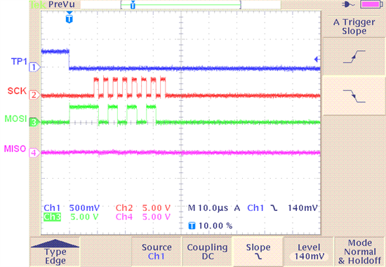
The problem is that it just sits there....forever. I am
monitoring the MOSI output with a scope and it goes high
once, but shows no other transitions. The emulator tells me
that LOSPCP still holds the 0x0002 I put there, and
PCLKCR0.8 (a.k.a. SPIAENCLK) is still set. All the other SPI
registers still show the values that I put in them:
SPICCR: 0x0087
SPICTL: 0x000E
SPISTS: 0x0000
SPIBRR: 0x007F
SPIRXEMU: 0x0000
SPIRXBUF: 0x0000
SPITXBUF: 0xFF00
SPIDAT: 0xFF00
SPIFFTX: 0x0000
SPIFFRX: 0x0000
SPIFFCT: 0x0000
SPIPRI: 0x0010
Can anybody see why this thing isn't working?
Thanks.