This thread has been locked.

If you have a related question, please click the "Ask a related question" button in the top right corner. The newly created question will be automatically linked to this question.

Booting from flash

Other Parts Discussed in Thread: CONTROLSUITE

Hi

Ibve been trying to understand how to set my F28027 controlSTICK to boot from flash I have been looking at several pdfs such as http://www.ti.com/lit/ug/sprufn6a/sprufn6a.pdf and they are very confusing.

Take for example the blinkingLED code that comes with ContrlSUITE in the relevant directory development kits directory, if I set the Active Build Configuration to Flash and load the program is there not some fixed set of steps I can use to get this program to run by itself the next time I plug the controlSTICK into the PC or apply power to it? 

I would have thought that the provided examples should work as if they were a fully working program, and thus, as recommended on the wiki have copied and altered one of these projects for the starting point o my current project, yet it seems I now have to wade through another mountain of guides and references and datasheets and wiki entries just to get the bloody thing to actually operate by itself!!

Thanks

  • Toby,

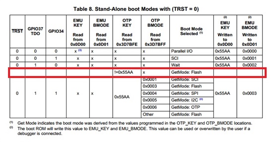
    On a fresh F2802x device, boot mode pins GPIO34 and GPIO37 are by default pulled up and the contents of TI OTP location (0x3D7BFE and 0x3D7BFF) will be in erased state. This would automatically get the device in boot to flash in standalone mode.

    But, if the device didn't enter boot to flash mode, check the contents of 0x3D7BFE and 0x3D7BFF.

    Regards,

    Manoj

  • Hi Manoj

    Many thanks for your reply

    The contents of both these locations is: FFFF    ITRAP1

    What should it be? how should it be changed?

    Thank you

  • Toby,

    To enter boot to flash mode, you don't need to change the contents of these locations. Just make sure to pull up GPIO34 and GPIO37 to enter boot to flash in standalone mode.

    In standalone mode, you won't be able to use emulator to check whether device enters boot to flash. You may to burn the code in flash and disconnect your JTAG, power cycle the board to check whether your application code is running as expected.

    Regards,

    Manoj

  • Hi Manoj

    If GPIO-34 is to be used by the program, then it cannot be held high forever so I guess there is some minimum amount of time it should be held high for. I assume once the device is booted and my code is running, that code can use the pin for what it wants?

    As I mentioned in my OP I am using a TI Piccolo ControlSTICK, on which GPIO37/TDO is pulled down as a comms line. Again it seems that this will need ot be pulled up for boot, then let free in case JTAG needs to be used.

    If I want to change EMU_KEY and EMU_BMODE to instead boot from Flash with the debugger connected is example #2 at the bottom of page 19 of http://www.ti.com/lit/ug/sprufn6a/sprufn6a.pdf the correct way to go about setting these registers?

    Again, thanks for you help Manoj

  • Toby,

    Yes, GPIO34 needs to be held high when you bring the device out of reset. Then it can be used in your program without any issues.

    If you want to BOOT TO FLASH with emulator connected, program 0x3D 7BFE with 0x55AA and program 0x3D 7BFF with 0x000B.

    Regards,

    Manoj

  • Hi Toby,

    I have been trying to program the flash on the controller of the C2000 Launchpad, but I haven't succeeded. I am trying to program the example ecap_capture_pwm from controlSUITE, and the after I have set the required files, these are the steps I follow:

    1. Before main function declared:
    extern Uint16 RamfuncsLoadStart;
    extern Uint16 RamfuncsLoadEnd;
    extern Uint16 RamfuncsRunStart;

    2. Add DSP2802x_MemCopy.c to the project

    3. After InitPieVectTable();, added statements:
    MemCopy(&RamfuncsLoadStart, &RamfuncsLoadEnd, &RamfuncsRunStart);
    InitFlash();

    4. Replaced 28027_RAM_lnk.cmd with F28027.cmd from ...\DSP2802x_common\cmd

    5. Compile the code

    6. Set the switch S1 in the board as ON ON OFF (110), and switch S2 set as ON.

    7. On CCSv6 press the Debug button and then the following error is shown:
    Error connecting to the target:
    (Error -1135 @ 0x0)
    The debug probe reported an error. Confirm debug probe configuration and connections, reset the debug probe, and retry the operation.
    (Emulation package 5.1.641.0)

    Without those changes, the code is loaded to the ram, and it runs fine.

    I have already checked the connection in the board, and it seems fine. Any suggestion to be able to load the code in the flash?

    Thanks in advance for any help you could provide.

    Best regards,
    Gus.