This thread has been locked.

If you have a related question, please click the "Ask a related question" button in the top right corner. The newly created question will be automatically linked to this question.

Overlapping PWMs triggered by external stimulus

Other Parts Discussed in Thread: CONTROLSUITE

Hello,

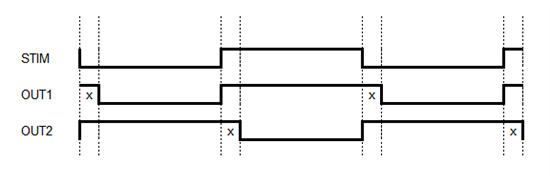
I'm trying to accomplish creating two PWMs triggered by an external stimulus. The signals need to overlap by a software controlled amount of time (x). The picture below shows the signals that I'm trying to generate with respect to the stimulus.

I've been looking at the Piccolo device's PWM module and it is not obvious to me that this can actually be done. Can you please give me some insight on how this can be done if at all.

The stimulus will switch no faster than 500 Hz. I'm looking for the value of x to be on the order of microseconds. I also need to make sure the timing is reliable cycle to cycle.

Thanks for your help.

Mike

  • Mike,

    Take a look at the deadband submodule in the Piccolo ePWM user's guide.  

    http://www.ti.com/lit/ug/spruge9e/spruge9e.pdf

    This will allow you to configure the waveforms to just be complimentary, and add "dead" periods inbetween transitions.  It will result in the behavior your are looking for.  We have some deadband examples available in controlSUITE as well.  You would need to configure an interrupt to setup the deadband according to the stimulus though.

    This may be possible using a DCEVT as well, but I will need to put some more thought into it.  If the external stimulus was either active low or active high you could pretty easily use a basic cycle by cycle trip to do this.

    Can you elaborate more on how the PWM outputs reflect the stimulus?  For example, is OUT1 ALWAYS high (except for the period x after the transition) while the stimulus is high?  Is OUT2 always opposite the stimulus (except for transition periods)?

    Kris

  • Kris,

    I'll take another look at the deadband module. It is also important to note that the frequency of the stimulus can change at any time.

    Kris Parrent said:
    For example, is OUT1 ALWAYS high (except for the period x after the transition) while the stimulus is high?

    OUT1 is ALWAYS high while the stimulus is high. When the stimulus transitions high to low after x seconds OUT1 goes low.

    Kris Parrent said:
    Is OUT2 always opposite the stimulus (except for transition periods)?

    OUT2 is ALWAYS high while the stimulus is low. When the stimulus transitions low to high after x seconds OUT2 goes low.

    The result of adding in the delay is so that the PWMs overlap by x seconds. So I suppose this is the opposite of a deadband.

  • Thank you.  I better understand your question now.  I'm going to play with this a bit before I throw out what I'm thinking.  I'll get back to you on the results.

    Just to clarify, the deadband will hold the value of the PWM for a defined length past where the normal edge would be, so it can be a high or low signal.

    Kris

  • There's a couple ways to do this.  The best solution I have at the moment is to connect your stimulus signal to the eCAP (you could probably use the ADC too, but I'm not as familiar with it).  You can configure the eCAP to interrupt on every changing edge and use this interrupt to force the PWM output to a specified state in the action qualifier by using the AQCSFRC register.  You can then use our usdelay() function to achiever your required delay, and force the other output low using the AQCSFRC register after the delay completes.  This is the easier way to implement but is somewhat manual.

    If you want the more complex route, still use the eCAP interrupt, but now use two PWM modules (i.e. EPwm1A and EPwm2A).  Now each eCAP ISR you use the force register to set each PWM output to the desired state.  This will affect the output from the action qualifier submodule which then sends the signals to the deadband submodule (reference Figure 20 http://www.ti.com/lit/ug/spruge9e/spruge9e.pdf).  Now if you configure the deadband submodule to have the desired falling edge delay on each of these PWM outputs, it will automatically take care of the delay for you whenever the corresponding signal has a falling edge.  This saves you from having to wait on the usdelay() function and doing another force.

    Please let me know if you have any questions.  There will be some small delay between the time of your stimulus and the time the output is seen on the PWMs.  But since you are only using a 500 Hz signal, it should be insignificant.  Does this seem acceptable?

    Kris

  • Hi Kris,

    Thanks for your help. I'm working on testing this out on a ControlCARD today. I'll let you know if I run in to any problems.

    Mike