This thread has been locked.

If you have a related question, please click the "Ask a related question" button in the top right corner. The newly created question will be automatically linked to this question.

TMS320F28335 CANB can not transmit any frame of data,

Other Parts Discussed in Thread: TMS320F28335, CODECOMPOSER

Hello,

I have CCSR 4.x and own  tms320F28335 based card.  Board IO, SCIs properties are working very well. I started to use CANA and CANB modules. For this, We connected CANA and CanB over  CANBUS transceivers and 120 Ohm terminating resistors. For software this I used TI's original "ecan_a_to_b_xmit" example. Yes it works  for CANA  I could  i see all of frame bits  on the line via Oscilascope and on pc  screen via USB to CANII int. inaterface adapter from IXXAT, As a next step i started to test CANB trasmitting instead of CANA ( i have just changed Cana...  into Canb...) but programme loops forever at 

       do
        {
          ECanbShadow.CANTA.all = ECanbRegs.CANTA.all;
        } while(ECanbShadow.CANTA.bit.TA25 == 0 );   // Wait for TA5 bit to be set..


Crystal freq: 23.9999 Mhz,,PLL 10, CANA.GPIO 30, 31  CANB: GPIO, 8,10

I did not change any settings i have just used "ecan_a_to_b_xmit"  examle code as is. I have checked "InitECanGpio();" and    "InitECan();"


There must be some magic for that CANB that i am not aware of that. I am sure CANB transcievers are OK, I measure signals from MCU pins. What is the reason of that CANB module's unexpected behaviour? Did anybody use that example for CANB to send any frame of data to CANA, and did it really work?

At the end my purpose is to develope a code one mini client-server programme between CANA-CANB. 

Thanks in advance,

IM

  • Hi! 

    i saw that you are working with CANA and you said that it is working correctly i'm doing the same but my network doesn't work could you tell me how you connected CANA over CANBUS transceivers and 120 ohm termination resistors and how you see the frame bits on pc screen throught these via USB to CANII int. interface adapter from IXXAT. I have a CAN to USB interface of grid connect maybe could work this device with the network. I would like that you shared with  me how  you made your network.

    please could you give TI's original "ecan_a_to_b_xmit" example.


    Thank you for your help

  • Hi,

    I have seen your posting right now. I'll prepare some document for you to help you. Before this let me answer some questions of you.

    I have made some modifications on TI's Ecan-CANB sample programme. I advice you try to make it run first "ecan_back2back" example then  other example "ecan_a_to_b_xmit". This examle codes exist in SPRC530.zip file from TI. Extract it, in C:\tidcs folder you can see  it,  just select proper MCU, CCS version -V4 or regular one. 

    I have seen frame data bits via a digital oscilascope and via software from IXXAT called MiniMon. That software -also simular programmes- are based on USB-CAN bus adapter. Software must have that adapters driver -software component in dll or lib or etc-. Nowadays i'll use Lawicell CANUSB adapter to develope a test software .

    For connection into CANBUS line, if you have USB_CAN adapter check it's wiring document -konnektor pin assigments. I suppose you have some board on it. and you have Can transceivers  -you must use can Transceiver for each can module of MCU -for example TMS320F28335 in my case-  we have used here own board not a board form digital spectrum or any other  card on market.

    In 1:1 CanBus connection just connect 120Ihm resistor at  both ends of line -High and Low Line)GND and shield must be connected into proper points check your canbus adapter and can transceiver's document.

    Line monitoring programme will monitor line and can also send some frames to Slave CAN Node.

    I tried to find my modified example but could not find it in this computer whenever i find it i'll post it. Please try to make your tests-developments step by step.  For a while i have stopped on working on that sample code this is why i have forgetted some details. My sample code may help you soon.

    Regards,

    IM

  • Hi!

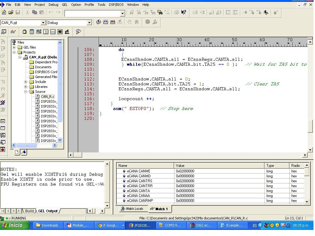
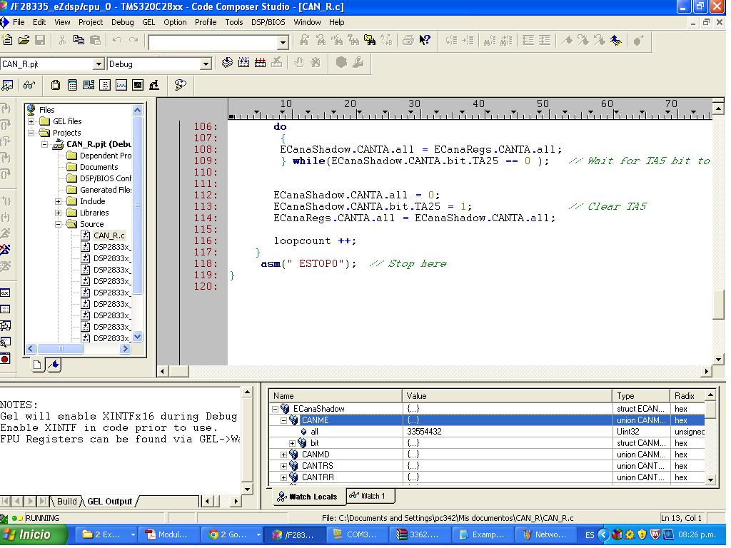
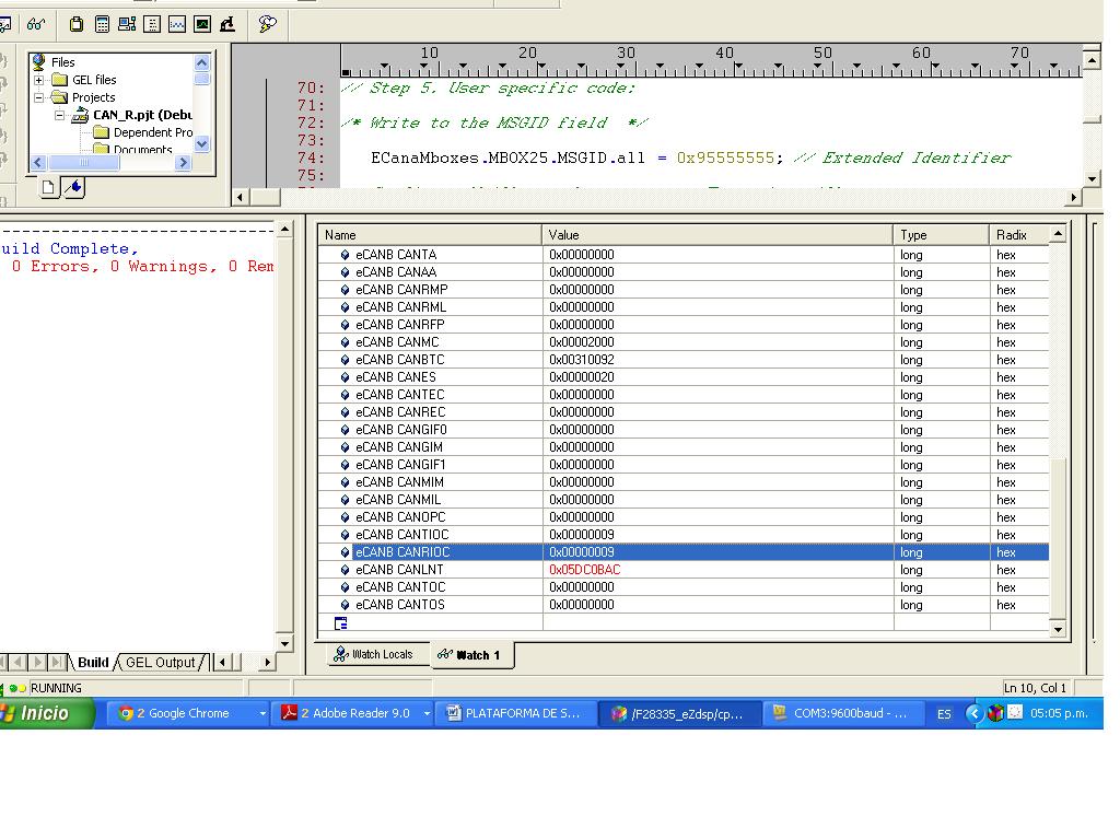
    I was following your suggestions, first of all i downloaded and run the example ecan_a_to_b_xmit, and looked up on the watch window  and this i what i had 


    For connections i have and USB adapter of gridconnect this device uses hyperterminal for send and receive messages on the network, this is the documentation of this device

     2022.CAN-USB-232_UM_800309_C.pdf

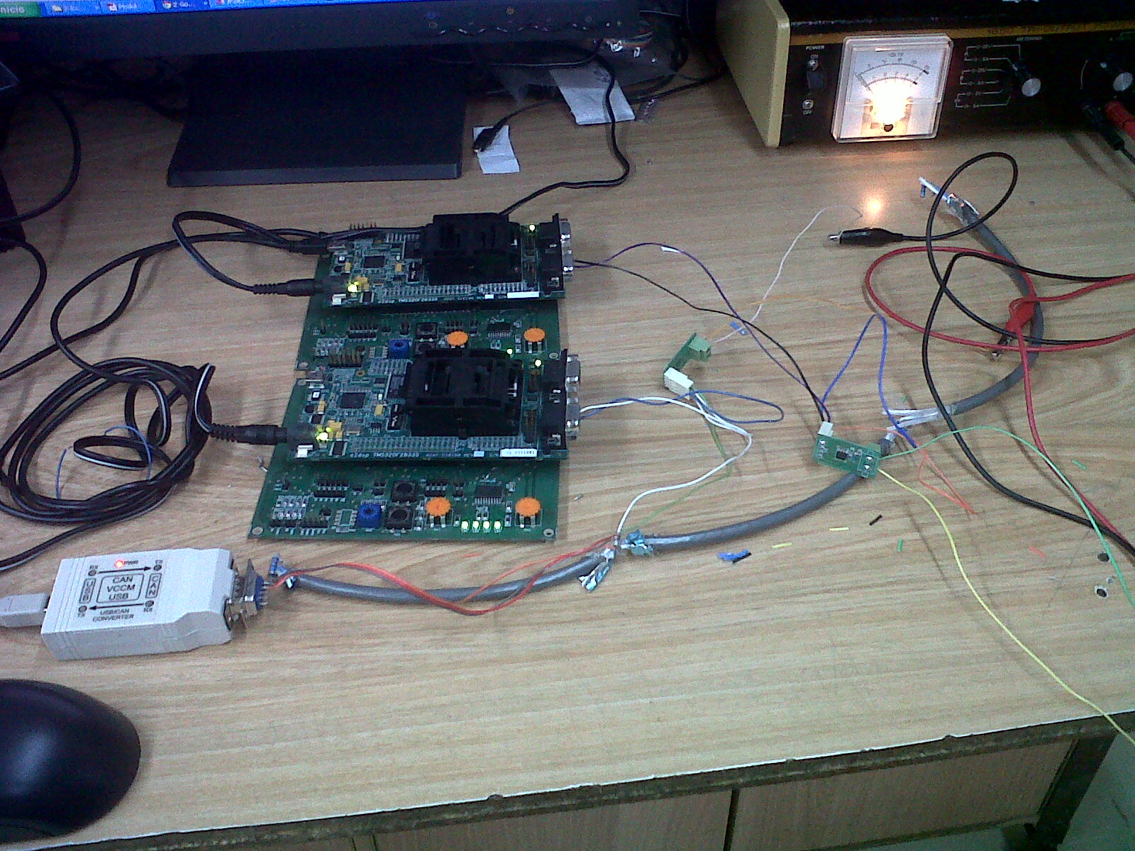
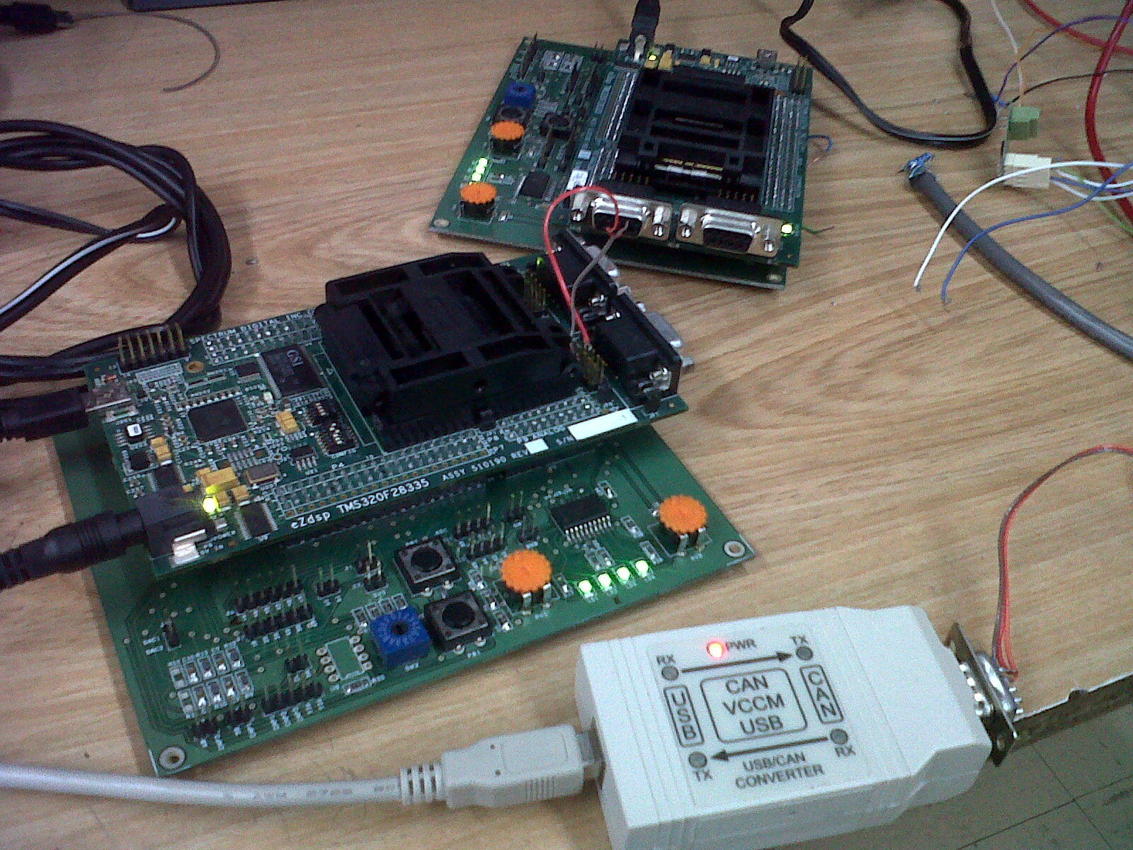
    Then the connections between the board TMS320F28335 and the transceivers is throught the connector DB9 (CANA) of the Board pins 2 and 7 to a transceiver pins D and R  (1 and 4) the other pins on the transceiver (Pins 7 and 6) CANH and CANL are connected to a network CAN throught a wire belden 9841. i Connected 120Ohm resistor at both ends of wire. i made the same for the other DSP .

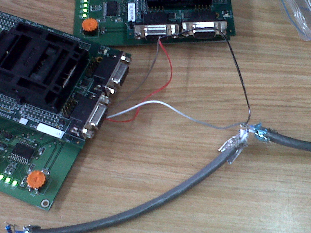
    This is the photo of my network 


    Finally i tried to send a message through the network on hyperterminal but there isn't happen. i don't know if the code is working, i read that i can test these looking the watch window but i don't know if the registers are ok


    Please could you help me!!


    Thank you

  • Hello,

    It seems you have two TMS320F28335 board from Spectrum Digital -or similar-. In my very short time -before meeting in the morning- let me advice something.

    If i were you.

    İ could connect each card together. Resistor may not be so important. Card A .   Can A, to Card B Can A.. In this way. from wathc window you can see. Watch window refreshing rate may not be suitable. CAN-RS232 adapter your are using what is the baudrate. You must check the baudrate. In RS232 versions baudrate may not include whle range (till 1MBps). In my monitoring adapter and sotware CAN-USB II case, in software i had to changing some settings, especillay autobaudrate detection etc. It was not so easy to start to monitor.  You may have some settings in your case.

    Frankly when i try on that canopen stuff sample and own board,

    I made it very hard please do things step by step,

    first test loopback example and  download it on board, see on watch window if it is woring and you see MsgIDs and some data. GPIO and inerface assignments must be correct all the time for sure.

    If you succeeded please go to enxt step  real data sending example.

    transmit XA to XB  example.  In this example you can see especilly sending of data from CANA easily. Whenever i have found my example i ll try to send it  to you -infact i have forgotten most of them anyway i also must try it for me.

    Please do not forget time diffrence in countries, here it Turkiye ) and do not loose your hope.

    Regards,

    IM

    PS: i ll check technical details of your CAN-RS232 adapter, by the way does not it have a specila programme for monitoring it must have focused on CAN montioring?

  • HI!!!

    I was following your instructions and i connected the board together like you said. i tested example Example_28xEcan_A_to_B_Xmit.c and looking i saw watch eCAN registers and i saw that eCANB CANLNT was working because each time change the register like that, may be this said me that the biard is receiving the message, it is ok?

    This said me that the communications between two boards are ok, nevertheless, i connected the transceivers on the same connector DB9 (P11) and J11 and the CAN-RS232 adapter but again doesn`t work. i don't know if the transceivers i have to connected like that. i was looking these file http://c2000.spectrumdigital.com/ezf28335/docs/ezdspf28335_schem.pdf  on page A-8 and the transceivers are connected on P11 and J11 but on the same place it is connected both board, cpould you tell where i have to connect the transceivers?

    My adapter CAN-Rs232 work  Tera Term VT (hyperterminal)  for monitoring the data on the network CAN, the communications is through COM port : The terminal must be configured for 9600 baud, 8-bits, no-parity, and 1 stop bit.

    i did these but the tera term doen't work.

    Thank you for your help, i really apreciate. Could you help me please

    This is my email may be you can send message or files: karolbernalcgmail.com   karitol860hotmail.com

    thank you so much

  • Hi,

    I do not know hod to add a file to this post. I have tried to do this in upper side side o fthis post but i think it did not work.

    Anyway;

    let me copy paste the example i tested -i brought my example form other computer- i hope this helps.

    Do not forget that i did not use EzDSP boards i used our develoepd board for a project.  I checked your CA-RS232 adapter it  can bu used to send and receive mesasage into -from can network.  There must not be any filter for can buses messages.

    But baud rates you said is very low , ,nsated of this hyperterminal and device muts be auto baudrate detection state otherwise it can not detect messages on it's board.

    This can happen event RS232 line observations!.  Please be aware of this. Instead of using that CNRS232 adapter try to use digital oscilascoe as i did and measure voltage between High and low or High to GND lines. This is the ost safe way to undertands and see communication. I am not so sure tha your adapter can monitor  directly or automatically a can network. In my case IXXAT USBto CANII adapter , i tried alot to discover how i ll see messages.  Please try to write adapter manufatcurer for  your observaion problem but vbefore this  check communiction signals in hardware via digital oscilascope. Just after this you can say something about your USB-CAN adapter. Talk to manufacturer ask theme how that adapter works, do you have to write some codes -progrmme- to obersve existing message traffic on a can network etc.

    If you run that example, -and  observe with oscilascope-  you will see at least one can node is sending a Message  to network. In my case problem was i could not recieve it on CANB, or I coud not send taht mesage from CANA to CanB. In anycase i clould not send any message from CanB. Oh yes this was my problem. )

    Let me hear from your tests.

     I could not find and definition of eCANB CANLNT register or variable. SO i could not make any comment on it.

    Regards,

    İsmail MISIR

  • Hi!!

    Thank you for your response, before to test your example, let me ask something:

    1. How do you connect the transceivers on the network? i was looking these file http://c2000.spectrumdigital.com/ezf28335/docs/ezdspf28335_schem.pdf  on page A-8 and the transceivers are connected on P11 and J11 but on the same place it is connected both board, could you tell me where i have to connect the transceivers?

    2. How do you know with code composer if CANA is sending a message. On watch window it is posiible to see on wich registers?

    3. When you observe on oscilloscope  you put one channel 1 on CANH pin 2 and channel 2 CANL pins 7 (connector DB9)?


    Thank you so much

    Regards

    Karol

  • Hello,

    Let me say,

    1-I do not use EZDSP based board. I use own board which you can see it in second picture. Can network and MCU CANModule also need only two lines and it works as differential.  So you need the wire just CAN H and CAN L, All CAN H pins to CAN H CanBus Netwrk line and all CANL pins to CAN L Network line. GND and Shield may be required to make  adapter etc to power, but teerminating resistor one must use at the both ends!

    I did check exDZP schematics -infact we derived own board by looking at this schematic -, there you can transceivers are already instaed and connected.

    But in your can network, let me say ezDSP card 1 and ezDSP card2.

    Please use both card's CANA line for simplicity.

    eZDSC Card1 -CANA  <--------> ezDSP Card2 Can A

    DB9F  - 7  ......................................... DB9F - 7    CanH Line connection

    DB9F  - 2  ......................................... DB9F - 2    CanL Line connection

    ezDSP 1 :R23 resitor termination resistor must be active so JP7 jumper must be active and short cut, so R23 ' one end on CANH line other end must be CAN H Line

    ezDSP 2 :R23 resitor termination resistor must be active so JP7 jumper must be active and short cut, so R23 ' one end on CANH line other end must be CAN H Line

     this is te connection.

    Rest of it, you must check that CANA module is activated wio GPIO connection (GPIO31 pin must be set for Perihperal 1 (ie CanA) not GPIO or XA17 and XA18. Infact CAN A transmşt B example will do this just check it.

    That is all for question 1, i hope it works.

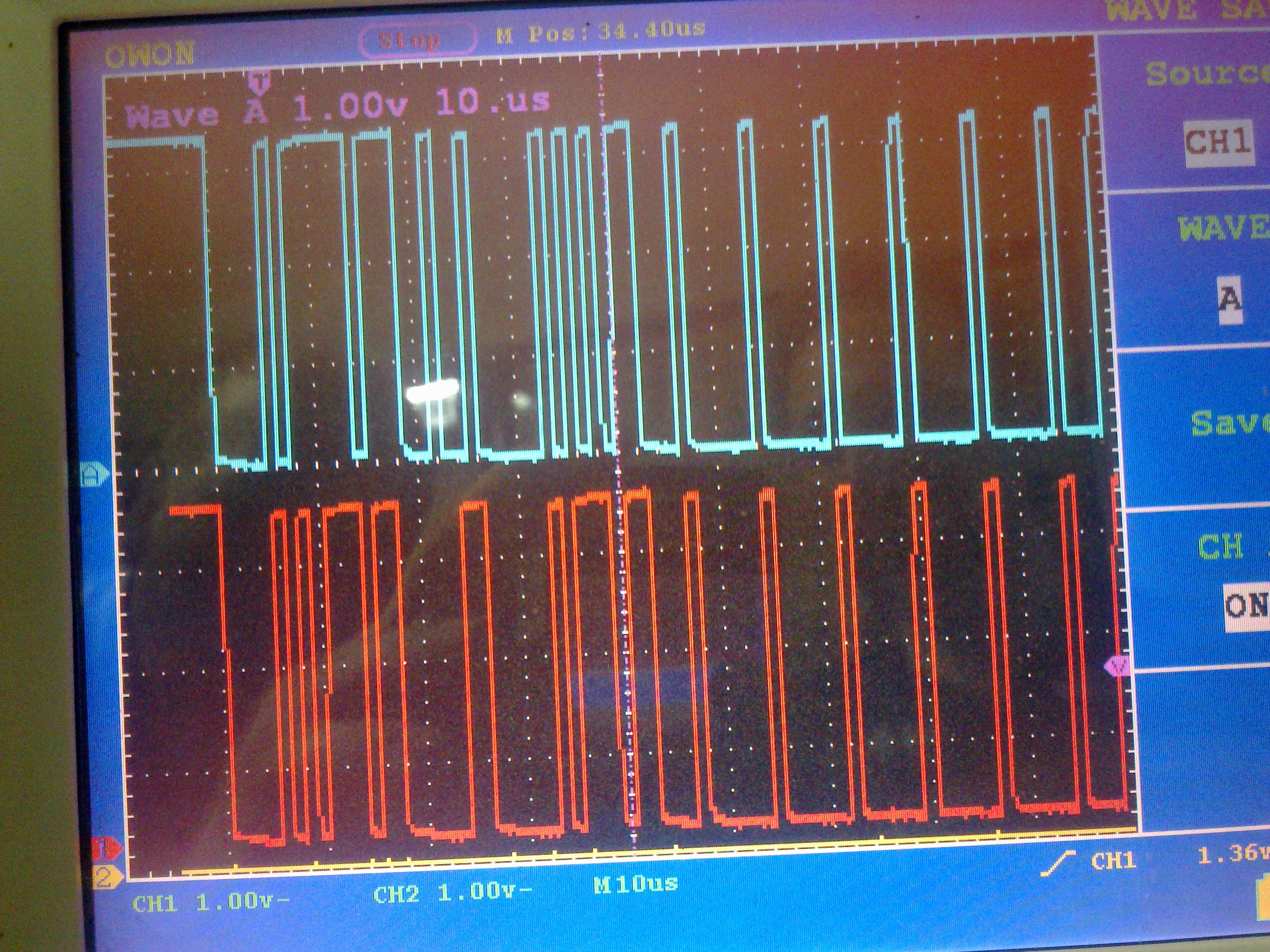
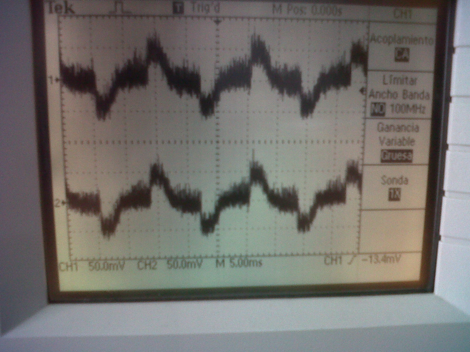
    3. With oscilasscope take cjannel 1, voltage measurement, x1  8cause voltage as i remember 3-5VDC you can see this on my oscilalscope view), Channel 1 probe  has two  terminal connec one of them to CANH, other terminal to CANL pins of CAN Network Line as in topmost picture of  my posts. You can not damage oscialsscope probes try to connect them CANH, and GND , CanL and GND. As i remember we have used probe termnals on CANH and CANB line of CAN NETWORK line. Just try this .Let picture 2 not confuse youin that picture i used two channels one CANA side other CanB side just for curious. One probe of channel was enough to see bytes-waveform.

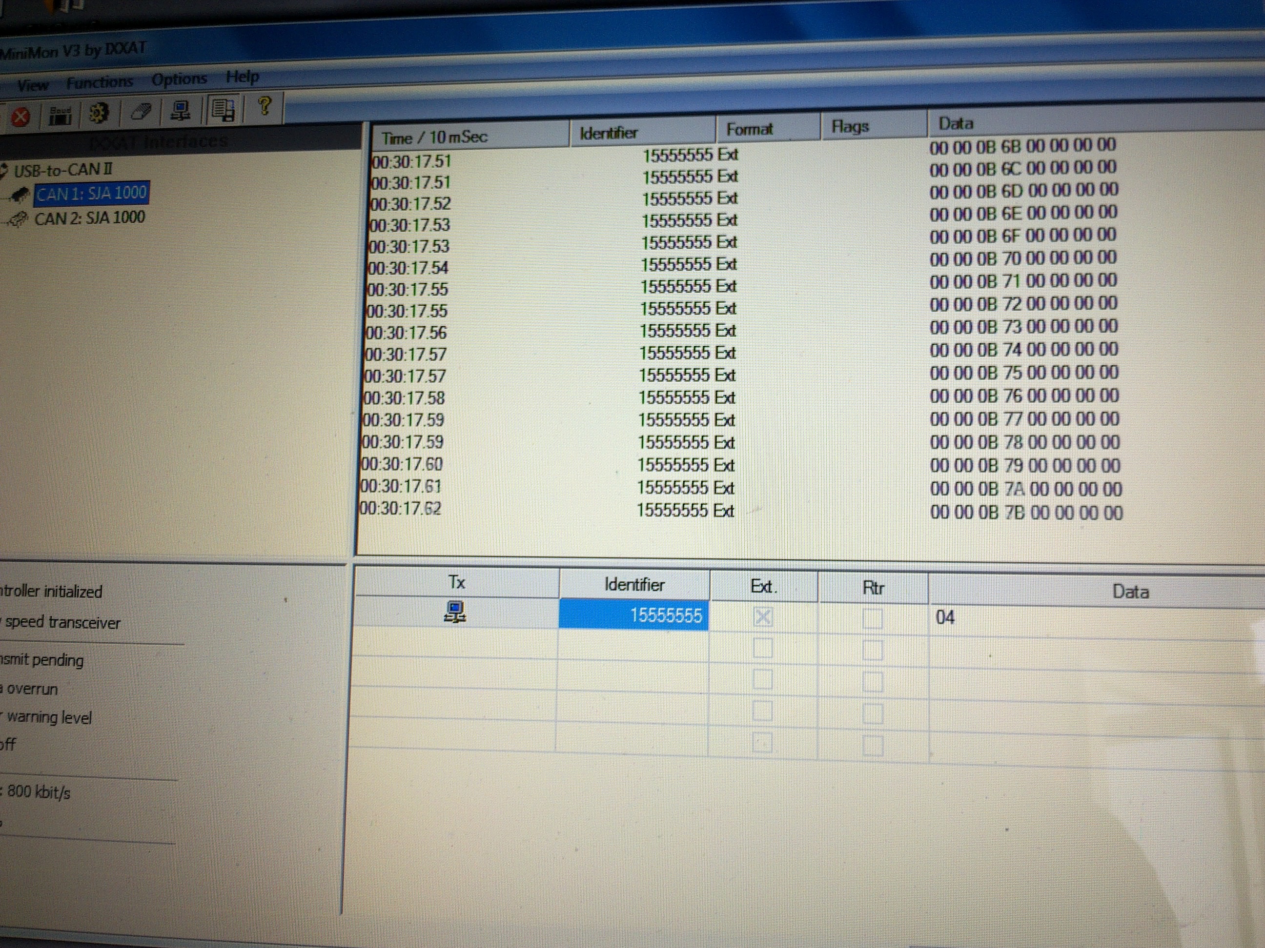
    In software observation i used MiniMon application programme from IXXAT, it has autobaudrate capability, i had to try to find how will i observe then finally i could see mesage frames including Header-ID, and rest of the frame including data (8 byte of data).In picture you can see MDL Love Byte 3 has variable data value i was changing

    in programme. Be sure the programme i sent you is not same programme i wanted to pass to some other step and i had to change it but soon i'll try to do same  thing at that time i can send it again to you. Nowadays i have focused on CanOpen protocol stack and aplication of it into my project this spends all my time.

    2. I do not remember this. But it is not a good idea to do this on  CSS watch window.

    If you want to prefer you want to see, conmpile your project in DEBUG mode _RAM_ type .CMD file,

                   do
                    {
                      ECanaShadow.CANTA.all = ECanaRegs.CANTA.all;
                    } while(ECanaShadow.CANTA.bit.TA25 == 0 );   // Wait for TA5 bit to be set..
            
    after this loop cretae a break point for a condition. Let this breakpoint include meaningfull  stuff. in each loop incease a variable  and

                   ECanbMboxes.MBOX25.MDL.all = 0x00000000;// WRITE some data here  and check this when it reaches breakpoint
                   ECanbMboxes.MBOX25.MDHall = 0x00000000;// WRITE some data here  and check this when it reaches breakpoint

    Remember that when there is an error on sending frame, program can not exit from upper loop.

    Sincerely,

    IM


  • Hi!

    Thank you so much for your reponse!

    1. When you said "there you can transceivers are already instaed and connected." this means that i don't need to use a Transceiver SN65HV230? i was looking these file

    http://www.ti.com/lit/ds/symlink/tms320f28335.pdf

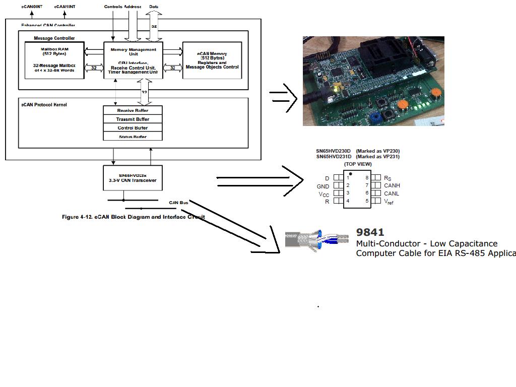
    on page 87 there are an eCAN Block Diagram and Interface Circuit i traduce like that

    Then i don't understand if i have to connect outside of the card a transceiver and the wire.

    Before i have these for make my network


    2. i was following your suggestions and i download  MiniMon application programme from IXXAT but there isn't CAN controller available on the side IXXAT interfaces, are you using another device different of both cards and oscilloscope?

    3. Are you using  MS0X3624A Agilent oscilloscope?


    Thank you so much , i really appreciate for your help


    Karol


  • Karol,

    Sorry for my mistyping in answer 1.

    Let me tell it again. I have checked ezDSP schematic. I have seen in that board you have transceivers there so you have right to connect them directly to a can network. You have those CAN transceivers already in your board. -page A8-. You must not add externally again those canbus transceivers. Picture you show, desribes TMS320F28335 MCU, MCU needs those trasnceivers and those transceivers have been placed on board. Just follow my pin to pin connections written in my previous post. Please see the picture i have warning for you.

    2. If you do not have IXXAT hardware USB to CAN II adapter, Minimon programme can not do anything for you. Cause MiniMon will research it's hardware to receive or transmit data frames to7from CanBus.

    3- I did use very cheap regular digital oscilascope.  That MS0X3624A oscialalscope from Agilent -x hewlet packard- is prett expensive and superious one. I do not have it )) infact you do not need such oscilascope to see data frame's existance on can network. Cause 1Mb/s baud rate is maximum for can network.

    4- For a couple of days i am trying on my board to make it work. I use CCS 5.2.x version -in old tests i was using CCS 4.x . I think in couple of days, i can make my board run for can bus communication at that time i can give  that source to you. Infact i must work immediately  but i have seen that i did not save sample code so i have chnaged it and changed code or codecomposer CCS 5.2.x gives some errors and i could not see data frame at can network.When i run CCS says " make sure PLC is not running in Limp Mode" . I try to solve this now i hope i ll solve it.

    5- I could run ecanloopback sample from TI, tidcs folder. In debug mode i have seen loopback is working. In Loppback mode,  data frames do not leave MCU and  no data at both side of can transceivers so you can not see any data frame at can network but it shows yes  in MCU can functionalty is operational and works.

    6- Please be sure can network is okay bpth end must have can devices. Ends must have 120 Ohm resistor. and just add your osccilasscope in the middle of lcan line time divisor let it be aorund 5-10 ns ...free scan... try to see frames.

    Regards,

    IM

  • Hello,

    This the programme file i could run. It is a  bit modified versionn of Ecan_A-transmit_B example.

    I have  addition of GPIO setting resetting just for debugging to see if programme is runnng or it is infinite loop and stucked. There must be at least two Can NODEs othewise can loop can not go out do while loops and it stucks.  I could see this from GPIO GPAIO. Bit 1 -there was led at the output of that bit.

    I hope this helps.

    Regards,

    IM


    #include "DSP28x_Project.h"     // Device Headerfile and Examples Include File

    #define TXCOUNT  5  // Transmission will take place (TXCOUNT) times...

    #define TRUE  1            
    #define FALSE 0    

    // Globals for this example
    long      i,ii,iii, iCanSentCount;
    long      iCanbErrStatus = 0;
    long       loopcount = 0;

    Uint32 iuCanaMSGIDShadow = 0;
    Uint32 iuCanaMSGIDNode = 0;
    Uint32 iuCanaMSGIDFunc = 0;

    Uint32 iuCanbMSGIDShadow = 0;
    Uint32 iuCanbMSGIDNode = 0;
    Uint32 iuCanbMSGIDFunc = 0;

    void delay_loop(void);
    void  Gpio_init(void);      


    void main()
    {

    /* Create a shadow register structure for the CAN control registers. This is
     needed, since, only 32-bit access is allowed to these registers. 16-bit access
     to these registers could potentially corrupt the register contents. This is
     especially true while writing to a bit (or group of bits) among bits 16 - 31 */

       struct ECAN_REGS ECanaShadow;
       struct ECAN_REGS ECanbShadow;

    // Step 1. Initialize System Control:
    // PLL, WatchDog, enable Peripheral Clocks
    // This example function is found in the DSP2833x_SysCtrl.c file.
       InitSysCtrl();

    // Step 2. Initalize GPIO:
    // This example function is found in the DSP2833x_Gpio.c file and
    // illustrates how to set the GPIO to it's default state.
    // InitGpio();  // Skipped for this example

       // Just initalize eCAN pins for this example
       // This function is in DSP2833x_ECan.c
       Gpio_init(); //GPIO optional

       InitECanGpio();
    //    InitECanaGpio();
    //    InitECanbGpio();
    // Step 3. Clear all interrupts and initialize PIE vector table:
    // Disable CPU interrupts
       DINT;

    // Initialize the PIE control registers to their default state.
    // The default state is all PIE interrupts disabled and flags
    // are cleared.
    // This function is found in the DSP2833x_PieCtrl.c file.
       InitPieCtrl();

    // Disable CPU interrupts and clear all CPU interrupt flags:
       IER = 0x0000;
       IFR = 0x0000;

    // Initialize the PIE vector table with pointers to the shell Interrupt
    // Service Routines (ISR).
    // This will populate the entire table, even if the interrupt
    // is not used in this example.  This is useful for debug purposes.
    // The shell ISR routines are found in DSP2833x_DefaultIsr.c.
    // This function is found in DSP2833x_PieVect.c.
       InitPieVectTable();

    // Interrupts that are used in this example are re-mapped to
    // ISR functions found within this file.

    // No interrupts used in this example.

    // Step 4. Initialize all the Device Peripherals:
    // This function is found in DSP2833x_InitPeripherals.c
    // InitPeripherals(); // Not required for this example

       // In this case just initalize eCAN-A and eCAN-B
       // This function is in DSP2833x_ECan.c
       InitECan();
    //   InitECana();
    //   InitECanb();
       
    EALLOW;
    SysCtrlRegs.PCLKCR0.bit.ECANAENCLK = 1;
    SysCtrlRegs.PCLKCR0.bit.ECANBENCLK = 1;
    EDIS;
    // Step 5. User specific code:

    /* Write to the MSGID field  */
       ECanaMboxes.MBOX25.MSGID.all =  0x00080000;//0x95555555; // Extended Identifier

    //  ECanbMboxes.MBOX25.MSGID.all = iuCanaMSGIDShadow;//0x95555555; // Extended Identifier
    //  ECanbMboxes.MBOX25.MSGID.all = 0x00080000; //iuCanbMSGIDShadow;//0x95555555; // Extended Identifier
    //CANA
    // Configure Mailbox under test as a Transmit mailbox
      ECanaShadow.CANMD.all = ECanaRegs.CANMD.all;
       ECanaShadow.CANMD.bit.MD25 = 0;
       ECanaRegs.CANMD.all = ECanaShadow.CANMD.all;
    // Enable Mailbox under test
       ECanaShadow.CANME.all = ECanaRegs.CANME.all;
       ECanaShadow.CANME.bit.ME25 = 1;
       ECanaRegs.CANME.all = ECanaShadow.CANME.all;
    // Write to DLC field in Master Control reg
       ECanaMboxes.MBOX25.MSGCTRL.bit.DLC = 8;
    // Write to the mailbox RAM field
       ECanaMboxes.MBOX25.MDH.all = 0x00000000;//0x55555555;


    //iuMSGIDNode = 0  ; iuMSGIDFunc = 128;  SYNC Mesg ID... Data =0  M -T  S - R
    //iuMSGIDNode = 4  ; iuMSGIDFunc = 0x700 ;  HeartBeat  Mesg ID... Byte 0 : State 0,4,5,127     M -R  S - T
    //iuMSGIDNode = 4  ; iuMSGIDFunc = 0x700 ;  NMT Boot-UP   Mesg ID... Byte 0 : State 0,4,5,127  M -R  S - T


    /* Begin transmitting */

      for(;;){
       //   loopcount = 1;
       for(i=0; i < TXCOUNT; i++)
       {
           //   ii = i%2 ;
           //   iii = i%10;


                   ECanaMboxes.MBOX25.MDL.all = loopcount; //0x55555555;

                   ECanaShadow.CANTRS.all = 0;
                   ECanaShadow.CANTRS.bit.TRS25 = 1;             // Set TRS for mailbox under test
                   ECanaRegs.CANTRS.all = ECanaShadow.CANTRS.all;
            
                   do
                    {
                      ECanaShadow.CANTA.all = ECanaRegs.CANTA.all;
                    } while(ECanaShadow.CANTA.bit.TA25 == 0 );   // Wait for TA5 bit to be set..
            
            
                   ECanaShadow.CANTA.all = 0;
                   ECanaShadow.CANTA.bit.TA25 = 1;                  // Clear TA5
                   ECanaRegs.CANTA.all = ECanaShadow.CANTA.all;
        //               }


        //These two GPIO setting-resetting lines are optional
        GpioDataRegs.GPASET.all    = BIT1;  //TEST LEDI DAIMA ON
               
         delay_loop();
        GpioDataRegs.GPACLEAR.all    = BIT1;  //TEST LEDI DAIMA ON

         delay_loop();

           loopcount ++;
        }
        delay_loop();
       }
         asm(" ESTOP0");  // Stop here
    }

    void delay_loop()
    {
        long      i;
        for (i = 0; i < 50000; i++) {}
    }

     void Gpio_init(void)
    {

       
        EALLOW;
        GpioCtrlRegs.GPAMUX1.all = 0x00111111;  // ePWM1A...6A,secildi, diger IO, Per2
        GpioCtrlRegs.GPAMUX2.all = 0x00000000;  // All GPIO
        GpioCtrlRegs.GPADIR.all = 0xFFFFFFFF;   // All outputs
        GpioCtrlRegs.GPBMUX1.all = 0x00000000;  // All GPIO
        GpioCtrlRegs.GPBMUX2.all = 0x00000000;  // All GPIO
        GpioCtrlRegs.GPBDIR.all = 0xA7FD55CB;   // All outputs BIT 11, 13, 9 DI, diger DO
        GpioCtrlRegs.GPCMUX1.all = 0x00000000;  // All GPIO
        GpioCtrlRegs.GPCMUX2.all = 0x000000;  // All GPIO
        GpioCtrlRegs.GPCDIR.all = 0xF7B4AA;   //(GPIO83) PIN 168, BIT 19 DI3
        EDIS;
         
    }

  • Hi!

    Thank you for your response,

    1. I was following your instructions of connection, i removed the transceivers and i tested with the program that you send me. These are the connections between the board and the wire.

    2. I observe the signals CANH and CANL with the oscilloscope, the results on the oscilloscope are these:

    * The signals must be complete square?

     * the signals are distorted may be for the noisy or these are not the result that we expected? 

    3. I donwload the  MiniMon application programme from IXXAT but   there isn't CAN controller available on the side IXXAT interfaces on the program, are you using another device for Minimon application??


    Thank you so much

    i really appreciate your help.


  • Hello,

    Waveform you have is just noise cause signal level is around 20mV in case of Canbus line those must be +3/-3V check my scope waveforms. This says me tehre is no canbus commucication or signal connection is bad. Be sure there must be at least two canbus nodes which one sending other one is receiving otherwise you can not see any signal! Please also use 120Ohm termiation resistor all teh time.

    MiniMon is a just a software it checks if you have a hardware on PCI, USB, etc port. If he finds it will start to use that hardware to reach canbus line. Please check my picture at left hand side you will see MiniMon has found USB-CN II interface adapter. If you do not have such a hardware there is no meaning to use MiniMon software.Your cabus adapter it must have a application programme enabling it to observe canbus activity on canbus line. Plese find it and use it.

    I see you do not use male-female d type connector when you are wiring to zDSP kit. Please use D type connector , solder your wires to this connector and plug that connector onto ezDSP kit's canbus connector. Weak connection may prevent communication or it may yield broken connection in worst case.!

    Regards,

    IM

  • Hi!!

    1. When you said that must be at least two canbus nodes this means that i need two cards and each of these are canbus nodes? i'm confused, for me one canbus node is a one card and the other card is the other node it is right? or i'm in the wrong way

    I download the program that you send me on each card, then  i connected to DB9 connector.

    I put some questions on the picture, please look at.

    Thank you So much

    Karol

  • Hello,

    I have send you an email and tried to explain some points here in picture.

    I hope it helps.

    IM

  • Hi!

    i´ve send you an email to explain the problems and the situation

    Thank you so much

    Karol

  • Hello,

    I got your email and responded it.

    I am working on canopen stack aplication -from Port- nowadays. They have some bugs or incompatiabilitis in their example projects. May be eclipse handling CCS projects does not work in a correct way. This weak side of TI IDE CCS R4-5! Compiling or linking searches a path which does not exist Conpiler or Linker path inludes! Probably it does not reset, refresh it's options!

    Hope to hear from you,

    IM

  • Hi ISM!

    Finally i can get a solution with your suggestions, so now i have a question to verify if the data that i'm sending through the USB CAN adapter is saving in a part of memory. I need to verify where is the data that i send. Could you help me with these.

    Thank you so much for your help

    Look at the software PCAN VIEW