This thread has been locked.

If you have a related question, please click the "Ask a related question" button in the top right corner. The newly created question will be automatically linked to this question.

Designing a controlCARD onto YOUR Application Baseboard

Other Parts Discussed in Thread: TMS320F28335

With the C2000 controlCARD development tools the controlCARD can easily be designed onto any application specific baseboard. We also recommend designing the XDS100 USB JTAG emulation onto your baseboard. Here's how you can put both of these onto your board.

Designing the controlCARD onto Your Baseboard

  1.       Choose the C2000 controlCARD you wish to design onto your board. All C2000 DIM100 controlCARDs have a common pinout, however C2000 MCUs have different peripherals so you will need to make certain you connect to the appropriate ones on your board. For example the F28335 has more PWMs than Piccolo, thus for compatibility you will need to ensure that the controlCARD PWM signals you wire up to your application board are common between Piccolo and the F28335. The baseline installer program (www.ti.com/c2000tools) includes the pintout table for every controlCARD located in C:\TI_F28xxx_SysHW. For example the Piccolo F28027 controlCARD pinout table can be found C:\TI_F28xxx_SysHW\CC2802xHWdevPkg\cC2802x-DIMM Pin-out table.pdf
  2. Design the MolexDIMM-100 connector onto your baseboard. The design for this and the pinout are both found in each controlCARD directory in the files MolexDIMM-100-876301001_sd.pdf and controlCARD-DIMM100-PinPositions.ppt
  3. That's it!

Designing the XDS100 Emulator onto Your Baseboard

The XDS100 emulator is an open source TI emulation technology that provides USB JTAG emulation at a very low cost. It is a full featured emulator that is slower than a traditional XDS510 class emulator, but is sufficient in most cases. It is found on all C2000 Experimenter's Kits.

  1. The C2000 XDS100 emulator design can be found on several C2000 development tools, however the simplest is the "USB docking station" found in the C2000 Experimenter's Kits. The emulator design can be found in the C:\TI_F28xxx_SysHW\DockingStn-HWdevPkg. This design also ties the SCI (UART) port of the C2000 MCU to the FTDI chip to allow the XDS1000 to act as both an emulator and a USB to serial bridge. If you need an isolated XDS100 emulator, please use the hardware design found in the TMDS1MTRPFCKIT baseboard. M1 is the isolated XDS100 emulator module.
  2. The FTDI chip that makes up the heart of the XDS100 emulator will need to be programmed. Please follow the instructions found in this forum post to program it. http://community.ti.com/forums/t/6237.aspx
  3. More information on the XDS100 can be found here http://tiexpressdsp.com/index.php/XDS100

Now your board has a built in USB JTAG emulator and a USB to serial bridge. It also can now use any C2000 controlCARD!

Feedback? Let me know!


  • Hi charlie,

    I am new to TI solution and controlCARD. If I don't misunderstand, what I need to do is designing a user customized motherboard which accepts controlCARD DIM100.

    1. If I don't have a JTAG emulator (blackhawk or spectrum), I must draw the XDS100 emulator by myself in order to use CCS communicating with controlCARD ?

    2. JTAG emulator is not a must ? But it helps developer to simulate and deploy their applications faster ? Technically, with the docking board and controlCARD, I have all required hardware to implement my code for control or something else?

    Thanks for your time,


  • HI Anh,

         We offer severl baseboard and controlCARD kits that include both a baseboard and a controlCARD. Once you move on to designing your own application specific baseboard you can simply design the DIM100 controlCARD slot onto your board and continue using the controlCARD.

          1) Yes, if you do not want to purchase an external emulator you will need to draw the XDS100 emulator out on your own customer board.

          2) Yes, you will need a JTAG emulator to program and ebug the C2000 MCU. You will either need an external emulator or you'll need to design an XDS100 onto your own baseboard. JTAG is the protocal that the C2000 MCU uses for development.

    Any other questions?

  • hi charlie,

    so i MUST but a thirdparty JTAG emulator like blackhawk or spectrum in order to debug my control card ? It a bit expensive for individual project !

    In that case, my question is why I need to design XDS100 emulator ?

    I read in the experimenter kit (OEM) that it has a USB JTAG emulator ? What is the different between them (JTAG and USB JTAG) ?

    If I buy a docking station (like "Delfino" F28335 TMDSDOCK28335 ), can I program the controlcard ? And how (with or without the emulator) ? If I plug this card on my application board and I want to deploy another board, I need only order the control card ? Is that right ?


    Sorry about all these question ? Because I do not want to make a mistake !


    Thank you very much,


  • The control card by itself cannot function at all without being plugged into a base socket and circuit board of some kind.  If your own design of a PCB that accepts a control card includes an XDS100 compatible circuit then you will just need to connect that XDS100 circuit between the PC and the JTAG port of the control card in order to debug and program the control card.

    If the PCB which accepts the control card does not include an XDS 100 type of JTAG-to-PC interface, it can still provide a JTAG connector which connects to the JTAG pins on the Control Card in the appropriate way so that you can connect an external JTAG-to-PC unit to that JTAG-pin-header and program / debug the control card.

    This product you mentioned:

    TMS320F28335 Experimenter Kit Status: ACTIVE

    TMDSDOCK28335


    Includes a control card, as well as an XDS100 compatible USB-to-JTAG interface for providing a connection between the PC and the JTAG interface of the control card when the control card is plugged into the dock board.  So you can then program / debug the control card from the connected PC with the appropriate software. 


    When you are done programming a control card and have uploaded your program into the FLASH memory of the control card's chip, you could turn off the control card / dock card power, remove the programmed control card, and place the programmed control card into another type of carrier board even if that other carrier board does not have a JTAG interface and does not have an XDS100 JTAG-to-PC interface.  The previously programmed control card will just work as it has been programmed to do in such a case, but of course cannot be programmed / debugged via JTAG in this situation.

    So if you buy the experimenter's kit, you can program any number of control cards with it, and you would not need to buy any other kind of external JTAG interface to the PC for control card development.

    If you want to have the capability to program or debug your control card while it is connected to your custom carrier board, you should design a JTAG header interface as part of your custom control card if you want to be able to program/debug using an external JTAG-to-PC interface.  This gives you flexibility at minimal expense / complexity cost when designing the custom carrier board, however it adds expense/inconvenience in requiring a distinct piece of JTAG-to-PC XDS100 or similar hardware.

    If you want to have the capability to program or debug your control card while it is connected to your custom carrier board, and you do not mind including the XDS100 circuit into your board's design, then you can simply incorporate that circuit onto your carrier card and then you'll be able to program / debug the control card with no additional JTAG-to-PC hardware.   Adding this capability to your custom PCB adds some complexity and expense to the carrier board design, though because of the addition of the XDS100 circuit.

    If you decide you want a higher performance / slightly higher functionality JTAG-to-PC interface then you can look at purchasing a more advanced JTAG-to-PC unit like one of the XDS510 type models from a vendor like Blackhawk, e.g. their USB2000 model or USB510L model.  Or of you just want an external less expensive XDS100 JTAG-to-PC unit you can just build the XDS100 circuit as a distinct project and not include it on your control card carrier board itself.  In these cases you'd need to provide the JTAG pin header interface circuit on your carrier boards, but would not include the XDS100 PC-to-JTAG circuit.

    I think buying or building an XDS100 type PC-to-JTAG programmer, and designing your carrier board with just a JTAG header but not including the XDS100 circuit on it will give you the most flexibility since you can more easily move your single XDS100 interface among many different carrier boards to debug / program them as long as they have JTAG headers.

    There is one other possibility which is perhaps even lower cost which is a device programming solution ONLY, and cannot be used for debugging.  I believe the C2000 chips have a Bootstrap Loader program in their ROMs which makes it possible to upload a program to the chip over the SCI-A [as I recall] serial port interface, provided that certain chip pins are wired in the fasion that selects this mode of boot/programming.  In this case you would just need a RS-232 interface on the carrier board between the control card's SCI port and the PC, and the serial programming software for the PC in order to upload an already prepared FLASH program image to the chip over the RS-232 UART SCI port.   To gain the benefits of better debugging, however, in addition to flash programming capability I suggest you get an XDS100 at least.


  • There has been some confusion as to where to find the XDS100 emulator on the schematics for the USB Docking Station. Download and install the Baseline Installer from www.ti.com/c2000tools. The Schematics for the USB docking station will be in C:\TI_F28xxx_SysHW\DockingStn-HWdevPkg. In the picture below I have highlighted the XDS100 emulator portion of the board.

    Charlie

  • Hi Charlie,


    we design a mechanized industrial plasma cutter source. After deep study we decide to use TMS320F28335 for interleaved PWM and control logic state machine.

    We need to use the isolated XDS100 emulator programming our custom board, you mention that  the hardware design found in the TMDS1MTRPFCKIT baseboard. (M1 is the isolated XDS100 emulator module) contains the baseboard and isolated XDS100 schematic and board design.

    Unfortunately unpacking the design I not found the baseboard design in it. Could you help our company to find it?

    Cheers,

    Antal

    design engineer


  • Antal,

            If you look in C:\TI_F28xxx_SysHW\Multi-Axis-HWdevPkg[R3] after installing the board specific software for the TMDS1MTRPFCKIT, page 3 of the "multi-AxisDMC-SCH[R3].pdf has the design for the isolated XDS100 emulator.

              I'd like to talk with you more about your design and why you chose the F28335. Can you send me an email at charles-ice at ti.com? Thanks!


    Charlie


  • hi there,

    finally, I can integrate the controlcard into my custom board. However, now the problem is where to buy this Dimm100 slot. It seems to me that was an old fashion standard. I look for this connector on digikey and farnell for months and did not find anything.


    Please if anyone has succesful integrated this control card into your custom board, tell me how you can carry on. Thank you very much.

  • Hello,

    TI has been using this socket from Mouser (http://www.mouser.com/ProductDetail/Molex/87630-1001/?qs=Oiu4OaXIaASlZhOLR%252b8uWA%3d%3d).  There are many of these in stock.

    Since the product is marked for obsolescence you can also use Mouser part number 538-71251-510.


    Thanks,
    Brett

  • Thank you Brett,


    You save my work.

    By the way, since TI wants to promote this kind of controlcard, I think it would be nice if TI can sell 2 or 3 socket for each sold ControlCard. This would be great for all developpers to really think about their custom board with TI card on its.

    Secondly, I see that the socket is quickly obsolete by changes in standard of memory socket. Maybe it will be nice if TI could upgrade this controlcard to the latest connector standard.


    Regards,

  • For a change I thought I will read the specifications of the 100pin DIMM socket. Look what I find.

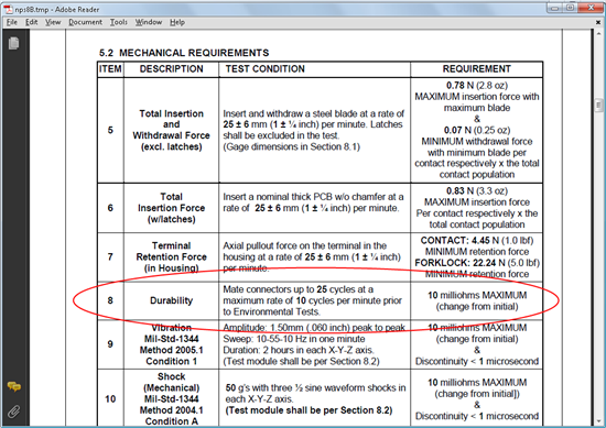
    Durability (mating cycles max)    25

    So after 25 insertions Molex is not with us to guarantee connections.

    good luck to all !!


    sunil

  • Sunil,

            I believe this is the document and spec you are referring to. This table is not saying after 25 insertions the connector is bad, but rather after 25 insertions done in the time frame they specify, the resistance between the connector and the board it is mated to changes by 10 milliohms maximum. Thus, as long as the two boards can handle the increased resistance then there is no problem. 

            From our usage here, we have only had one connector fail and it was the one on our test board, where all of our controlCARDs are tested. It failed after around 4,000 insertion cycles. 

    I hope this helps! Also, in mid-July TI will start offering the DIM100 connector as an accessory to our tools. We have also discussed the connector with Molex and there are no plans to end of life it at this time. Last I checked Mouser has over 1000 in stock. 

    Charlie


  • Charlie,

    No that is not the line of spec I was reading. One I read is right on the first page.

     25 insertion limit may not be too bad because  in a real practical production situation 25 insertions may be enough and  other connectors I looked into  have 25-50 insertion limit.

    But your comments here compels me to share the email reply I had from Molex.


    Hello Sunil,


    Correct, it is rated to 25 mating cycles.  Exceeding this rating may results in a degraded connection.


    Regards,


    Ryan Sheahen


    Associate Sales Engineer

    Molex Incorporated

    2222 Wellington Ct.

    Lisle, IL 60532

    Ph: 1-800-786-6539 [ext. 555-2120]

    Ryan.Sheahen@Molex.com

    www.Molex.com


  • Hi Charlie,

    Can we use XDS100 without CCS.in other words I need a programmer that program 28335 without CCS(for example program flash of 28335 with a software that doesn't need CCS).

    you produce XDS100 as open source emulator,It's very good.But it seems that this emulator needs CCS to work.But I need a JTAG programmer that work with a software that doesn't need CCS.because when I write my program and debug it and final it,I have to run CCS and connect to DSP then reset it and then program it after these I must disconnect and for another DSP do those things again,It's too hard.

    do you have any suggestion.

    thanks

  • You might want to contact the folks at codeskin.  They recently ported their c2prog programmer to the XDS100.

    http://www.codeskin.com/

    Also if you are going to be programming a lot of devices, consider a gang programmer like the one from blackhawk.  It doesn't use the XDS100, but if there are a large number of parts involved it may be worth the investment:

    http://www.blackhawk-dsp.com/downloads/docs/appnotes/BH-GANG2000-TA-01.pdf

    Regards

    Lori


  • Ali:

    You could also consider the Elprotronic FlashPro2000 (www.elprotronic.com) - standalone programming of C2000 parts without CCS.

    Regards,

    Todd Anderson

  • Dear Lori.
    I'm sorry for answering you too late.
    I contact the codeskin technical support and they answer me,so my problem is solved.
    thanks for your recommendation.
    with best regards
    Ali

  • Hi Todd,

    I solved my problem with C2prog.thanks for your recommendation.

    with best regards,

    Ali