This thread has been locked.

If you have a related question, please click the "Ask a related question" button in the top right corner. The newly created question will be automatically linked to this question.

CAN communication problem

Hi,

I am doing a motor control application with 24 motors. Each motor is driven by a TMS320F38035 controller. All the controllers are networked with CAN. The configuration is as shown below.

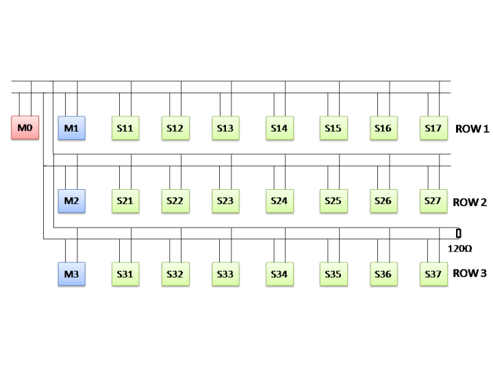
M0 is the control card and it is driving M1, M2 and M3. M1 is the master of S11 to S17 and M2 is the master of S21 to S27 and so on. For that I have configured three mailboxes in M0 for transmission. M1, M2 and M3 is configured with 8 mailboxes, 1 for reception (from M0) and 7 for transmission (for Sn1 to Sn7).
For the initial testing I started connecting with only one row at a time. When I connected only the first row, everything worked fine. M0 communicated with M1 and M1 communicated with S11 to S17. The same I repeated for the second and the third row.
In the next step, I connected two rows at a time. But when I connected the second row along with the first, there are some problems. M1 can communicate with S11 to S17 and M2 can communicate with S21 to S27 before turning on the M0. When M0 is switched on the communication stops. If I disconnect M2 from the network there is no problem. What could be the reason for this? Could someone identify what the problem is? It seems like when M0 communicates with M1 and M2 which are already the masters of their corresponding slaves, M0 could not send data to them. Is there any thing which I should consider when a controller is sending and receiving data at the same time via CAN?

  • sorry for the typo. The controller is not F38035, its F28035.

  • Tinto,

    As you know already, CAN is a multi-master bus and  bus-arbitration is done on the message-ID. How do you add a new node? And when you add, do you see error-frames the bus or the lines stuck in some state?. Can 2 nodes be using the same message ID and getting CRC errors?

    Note: I believe you need to terminate both ends.

    Thanks,

    Joe

  • Joe, 

    I am using the following message IDs for each node:

    M1 = 0x9555AAA0

    M2 = 0x9555AAA1

    M3 = 0x9555AAA2

    S11 = 0x9555AA10

    S12 = 0x9555AA20

    S13 = 0x9555AA30

    S14 = 0x9555AA40

    S15 = 0x9555AA50

    S16 = 0x9555AA60

    S17 = 0x9555AA70

    S21 = 0x9555AA11

    S22 = 0x9555AA21

    S23 = 0x9555AA31

    S24 = 0x9555AA41

    S25 = 0x9555AA51

    S26 = 0x9555AA61

    S27 = 0x9555AA71

    S31 = 0X955AA12

    S32 = 0X955AA22

    S33 = 0X955AA32

    S34 = 0X955AA42

    S35 = 0X955AA52

    S36 = 0X955AA62

    S37 = 0X955AA72

    So none of them uses the same message IDs. When I am connecting only the first row, only one mailbox is configured in M0 (with 0x9555AAA0, which is the message ID for M1).  M1 is configured with 7 mailboxes for transmit (with the message IDs for S11 to S17). Then I could see that communication is proper. When I add the second row, I configure one more mailbox in M0 with message ID 0x9555AAA1 (for M2). M2 is configured with 7 mailbox for transmit (S21 to S27). When this second row is connected, can transmission stops. When I disconnect only the M2 from the two rows, communication starts again (no other change is made). If I connect the second row or third row alone, there is no problem. 

    How could I see whether there are CRC errors or error frames? Currently I have termination resistor at one end only. Could that create these kind of errors?

    Thanks, 

    Tinto

  • Hi Tinto,

    This can happen sometimes when different nodes are switched on at different times. Because of power sequencing, pins might have a glitch and CAN bus errors build up finally causing the bus to turn off. Set the ABO bit in CANMC register during CAN peripheral initialisation for all the nodes. See if that helps. 

    Also connect termination resistors at 2 ends of the bus. But not sure whether that's the problem.

    All the best,

    Vivek

  • 1.) Check, if your physical layout (termination, loads,etc) is according to the CAN standard. Your schematics shows open ends of some of your can sections, which is a "no go".  Same is valid for your "star"- shaped layout of 3 branches. 

    2.) Your list of Identifiers is wrong. Some are 32-bit long, but CAN supports 29 bit maximum.