This thread has been locked.

If you have a related question, please click the "Ask a related question" button in the top right corner. The newly created question will be automatically linked to this question.

how to probe CAN module in TMS320F28335

Other Parts Discussed in Thread: TMS320F28335, SN65HVD230, SN65HVD235

Hi!

I'm working with CAN module i make the program on code composer studio and there aren't errors, i connected to transceiver the connector DB9 to  twisted pair of lines with the correspondig termination (resistances 120). i don't know how to send the frame messages and how to see them. 

Anybody could help me how to probe the CAN network with TMS320F28335?


Thank you

#include "DSP2833x_device.h"
// external function prototypes
extern void InitSysCtrl(void);
extern void InitPieCtrl(void);
extern void InitPieVectTable(void);
extern void InitCpuTimers(void);
extern void InitECan(void);	
extern void ConfigCpuTimer(struct CPUTIMER_VARS *, float, float);

void Gpio_select(void);
interrupt void cpu_timer0_isr(void);


void main (void) 
{

int counter=0;
struct ECAN_REGS ECanbShadow; //used as a local copy of the original CAN registers
InitSysCtrl(); // Initialize the CPU


EALLOW;

SysCtrlRegs.PCLKCR0.bit.ECANBENCLK = 1;  // eCAN-B

EDIS;

EALLOW; // Enable EALLOW protected register access, is possible to write freely in this protected registers
SysCtrlRegs.WDKEY = 0x55;
SysCtrlRegs.WDKEY = 0xAA;
EDIS;


Gpio_select(); // function GPIO30 as TX and GPIO31 as RX

InitECan(); // initialization CAN module


//preparation the transmit mailbox 
ECanbMboxes.MBOX5.MSGID.all     = 0x10000000; //identifier
ECanbMboxes.MBOX5.MSGID.bit.IDE = 1;  //extended identifier

// configure mailbox 5

ECanbShadow.CANMD.all = ECanbRegs.CANMD.all;
ECanbShadow.CANMD.bit.MD5 = 0;
ECanbRegs.CANMD.all = ECanbShadow.CANMD.all;

// enable mailbox #5

ECanbShadow.CANME.all = ECanbRegs.CANME.all;
ECanbShadow.CANME.bit.ME5 = 1;
ECanbRegs.CANME.all = ECanbShadow.CANME.all;

// Data Length Code Field (DLC) in Message Control Register

ECanbMboxes.MBOX5.MSGCTRL.all = 0; //clear all reiaming bits of this register
ECanbMboxes.MBOX5.MSGCTRL.bit.DLC = 1;

ECanbMboxes.MBOX5.MSGID.all     = 0x10000000;	// message identifier 
ECanbMboxes.MBOX5.MSGID.bit.IDE = 1;  // Extended Identifier

InitPieCtrl();		// basic setup of PIE table; from DSP2833x_PieCtrl.c
	
InitPieVectTable();	// default ISR's in PIE

	EALLOW;
	PieVectTable.TINT0 = &cpu_timer0_isr;
	EDIS;

	InitCpuTimers();	// basic setup CPU Timer0, 1 and 2

	ConfigCpuTimer(&CpuTimer0,150,100000);

	PieCtrlRegs.PIEIER1.bit.INTx7 = 1;

	IER |=1;

	EINT;
	ERTM;

	CpuTimer0Regs.TCR.bit.TSS = 0;	// start timer0


ECanbMboxes.MBOX5.MDL.byte.BYTE0=counter; 
ECanbShadow.CANTRS.all=0;
ECanbShadow.CANTRS.bit.TRS5=1; // set the TRS(n) bit to 1 to start the transmission
ECanbShadow.CANTRS.all=ECanbShadow.CANTRS.all;

while(1)
	{    
	  		while(CpuTimer0.InterruptCount < 10)	// wait for 10*100 milliseconds
			{
				EALLOW;
				SysCtrlRegs.WDKEY = 0xAA;	// service WD #2
				EDIS;
			}
			CpuTimer0.InterruptCount = 0;

			ECanbMboxes.MBOX5.MDL.byte.BYTE0 = counter & 0x00FF ;
     		ECanbShadow.CANTRS.all = 0; 	
     		ECanbShadow.CANTRS.bit.TRS5 = 1;     // Set TRS for mailbox under test       
     		ECanbRegs.CANTRS.all = ECanbShadow.CANTRS.all; 

			while(ECanbRegs.CANTA.bit.TA5 == 0 ) // Wait for TA5 bit to be set.
     		{
				EALLOW;
				SysCtrlRegs.WDKEY = 0xAA;				// Service watchdog #2
				EDIS;
     		} 
			   
	     	ECanbShadow.CANTA.all = 0; 	
	     	ECanbShadow.CANTA.bit.TA5 = 1;     	 // Clear Transmit Acknowledge #5       
	     	ECanbRegs.CANTA.all = ECanbShadow.CANTA.all;
			
			counter++;
			GpioDataRegs.GPBTOGGLE.bit.GPIO34 = 1;		// toggle red LED LD3 @ 28335CC

     }
  

}

void Gpio_select(void)
{
   
    EALLOW;
	GpioCtrlRegs.GPAMUX1.all = 0;		// GPIO15 ... GPIO0 = General Puropse I/O
	GpioCtrlRegs.GPAMUX2.all = 0;		// GPIO31 ... GPIO16 = General Purpose I/O
	
	GpioCtrlRegs.GPAMUX2.bit.GPIO30 = 1;	// Enable pull-up for GPIO30  (CANRXA)
	GpioCtrlRegs.GPAMUX2.bit.GPIO31 = 1;	// Enable pull-up for GPIO31  (CANTXA) 

	GpioCtrlRegs.GPBMUX1.all = 0;		// GPIO47 ... GPIO32 = General Purpose I/O
	GpioCtrlRegs.GPBMUX2.all = 0;		// GPIO63 ... GPIO48 = General Purpose I/O
	GpioCtrlRegs.GPCMUX1.all = 0;		// GPIO79 ... GPIO64 = General Purpose I/O
	GpioCtrlRegs.GPCMUX2.all = 0;		// GPIO87 ... GPIO80 = General Purpose I/O
	 
	GpioCtrlRegs.GPADIR.all = 0;
	GpioCtrlRegs.GPADIR.bit.GPIO9 = 1;	// peripheral explorer: LED LD1 at GPIO9
	GpioCtrlRegs.GPADIR.bit.GPIO11 = 1;	// peripheral explorer: LED LD2 at GPIO11

	GpioCtrlRegs.GPBDIR.all = 0;		// GPIO63-32 as inputs
	GpioCtrlRegs.GPBDIR.bit.GPIO34 = 1;	// peripheral explorer: LED LD3 at GPIO34
	GpioCtrlRegs.GPBDIR.bit.GPIO49 = 1; // peripheral explorer: LED LD4 at GPIO49
	GpioCtrlRegs.GPCDIR.all = 0;		// GPIO87-64 as inputs
	
	EDIS;
}

interrupt void cpu_timer0_isr(void)
{
	CpuTimer0.InterruptCount++;
	EALLOW;
	SysCtrlRegs.WDKEY = 0x55;	// service WD #1
	EDIS;
	PieCtrlRegs.PIEACK.all = PIEACK_GROUP1;
}


  • Hi Karol,

    I suggest you to look at the Can loopback example for TMS320F28335 that comes in control Suite. You'll get some clarity there. Both hardware connections and software flow will be described there.

    Vivek

  • hi! i'm testing my network CAN with transceiver SN65HVD230 but when i tested the output voltaje of the module (connector DB9) the value in the pin 2 and 7 are 22.9 could be the problem? what i have to do if it's the problem?

    i only has a one node can i probe with them?

    Thank you

  • Hi Karol,

    You cannot operate Can module with just a single node attached on the bus. For effective communication to happen, there needs to be atleast 2 nodes on the bus.

    Vivek

  • hi!

    But in one module there are this program:

    #include "DSP2833x_device.h"
    // external function prototypes
    extern void InitSysCtrl(void);
    extern void InitPieCtrl(void);
    extern void InitPieVectTable(void);
    extern void InitCpuTimers(void);
    extern void InitECan(void);
    extern void ConfigCpuTimer(struct CPUTIMER_VARS *, float, float);

    void Gpio_select(void);
    interrupt void cpu_timer0_isr(void);


    void main (void)
    {

    int counter=0;
    struct ECAN_REGS ECanbShadow; //used as a local copy of the original CAN registers
    InitSysCtrl(); // Initialize the CPU


    EALLOW;

    SysCtrlRegs.PCLKCR0.bit.ECANBENCLK = 1; // eCAN-B

    EDIS;

    EALLOW; // Enable EALLOW protected register access, is possible to write freely in this protected registers
    SysCtrlRegs.WDKEY = 0x55;
    SysCtrlRegs.WDKEY = 0xAA;
    EDIS;


    Gpio_select(); // function GPIO30 as TX and GPIO31 as RX

    InitECan(); // initialization CAN module


    //preparation the transmit mailbox
    ECanbMboxes.MBOX5.MSGID.all = 0x10000000; //identifier
    ECanbMboxes.MBOX5.MSGID.bit.IDE = 1; //extended identifier

    // configure mailbox 5

    ECanbShadow.CANMD.all = ECanbRegs.CANMD.all;
    ECanbShadow.CANMD.bit.MD5 = 0;
    ECanbRegs.CANMD.all = ECanbShadow.CANMD.all;

    // enable mailbox #5

    ECanbShadow.CANME.all = ECanbRegs.CANME.all;
    ECanbShadow.CANME.bit.ME5 = 1;
    ECanbRegs.CANME.all = ECanbShadow.CANME.all;

    // Data Length Code Field (DLC) in Message Control Register

    ECanbMboxes.MBOX5.MSGCTRL.all = 0; //clear all reiaming bits of this register
    ECanbMboxes.MBOX5.MSGCTRL.bit.DLC = 1;

    ECanbMboxes.MBOX5.MSGID.all = 0x10000000; // message identifier
    ECanbMboxes.MBOX5.MSGID.bit.IDE = 1; // Extended Identifier

    InitPieCtrl(); // basic setup of PIE table; from DSP2833x_PieCtrl.c

    InitPieVectTable(); // default ISR's in PIE

    EALLOW;
    PieVectTable.TINT0 = &cpu_timer0_isr;
    EDIS;

    InitCpuTimers(); // basic setup CPU Timer0, 1 and 2

    ConfigCpuTimer(&CpuTimer0,150,100000);

    PieCtrlRegs.PIEIER1.bit.INTx7 = 1;

    IER |=1;

    EINT;
    ERTM;

    CpuTimer0Regs.TCR.bit.TSS = 0; // start timer0


    ECanbMboxes.MBOX5.MDL.byte.BYTE0=counter;
    ECanbShadow.CANTRS.all=0;
    ECanbShadow.CANTRS.bit.TRS5=1; // set the TRS(n) bit to 1 to start the transmission
    ECanbShadow.CANTRS.all=ECanbShadow.CANTRS.all;

    while(1)
    {
    while(CpuTimer0.InterruptCount < 10) // wait for 10*100 milliseconds
    {
    EALLOW;
    SysCtrlRegs.WDKEY = 0xAA; // service WD #2
    EDIS;
    }
    CpuTimer0.InterruptCount = 0;

    ECanbMboxes.MBOX5.MDL.byte.BYTE0 = counter & 0x00FF ;
    ECanbShadow.CANTRS.all = 0;
    ECanbShadow.CANTRS.bit.TRS5 = 1; // Set TRS for mailbox under test
    ECanbRegs.CANTRS.all = ECanbShadow.CANTRS.all;

    while(ECanbRegs.CANTA.bit.TA5 == 0 ) // Wait for TA5 bit to be set.
    {
    EALLOW;
    SysCtrlRegs.WDKEY = 0xAA; // Service watchdog #2
    EDIS;
    }

    ECanbShadow.CANTA.all = 0;
    ECanbShadow.CANTA.bit.TA5 = 1; // Clear Transmit Acknowledge #5
    ECanbRegs.CANTA.all = ECanbShadow.CANTA.all;

    counter++;
    GpioDataRegs.GPBTOGGLE.bit.GPIO34 = 1; // toggle red LED LD3 @ 28335CC

    }

    }

    void Gpio_select(void)
    {

    EALLOW;
    GpioCtrlRegs.GPAMUX1.all = 0; // GPIO15 ... GPIO0 = General Puropse I/O
    GpioCtrlRegs.GPAMUX2.all = 0; // GPIO31 ... GPIO16 = General Purpose I/O

    GpioCtrlRegs.GPAMUX2.bit.GPIO30 = 1; // Enable pull-up for GPIO30 (CANRXA)
    GpioCtrlRegs.GPAMUX2.bit.GPIO31 = 1; // Enable pull-up for GPIO31 (CANTXA)

    GpioCtrlRegs.GPBMUX1.all = 0; // GPIO47 ... GPIO32 = General Purpose I/O
    GpioCtrlRegs.GPBMUX2.all = 0; // GPIO63 ... GPIO48 = General Purpose I/O
    GpioCtrlRegs.GPCMUX1.all = 0; // GPIO79 ... GPIO64 = General Purpose I/O
    GpioCtrlRegs.GPCMUX2.all = 0; // GPIO87 ... GPIO80 = General Purpose I/O

    GpioCtrlRegs.GPADIR.all = 0;
    GpioCtrlRegs.GPADIR.bit.GPIO9 = 1; // peripheral explorer: LED LD1 at GPIO9
    GpioCtrlRegs.GPADIR.bit.GPIO11 = 1; // peripheral explorer: LED LD2 at GPIO11

    GpioCtrlRegs.GPBDIR.all = 0; // GPIO63-32 as inputs
    GpioCtrlRegs.GPBDIR.bit.GPIO34 = 1; // peripheral explorer: LED LD3 at GPIO34
    GpioCtrlRegs.GPBDIR.bit.GPIO49 = 1; // peripheral explorer: LED LD4 at GPIO49
    GpioCtrlRegs.GPCDIR.all = 0; // GPIO87-64 as inputs

    EDIS;
    }

    interrupt void cpu_timer0_isr(void)
    {
    CpuTimer0.InterruptCount++;
    EALLOW;
    SysCtrlRegs.WDKEY = 0x55; // service WD #1
    EDIS;
    PieCtrlRegs.PIEACK.all = PIEACK_GROUP1;
    }

    but in the other microcontroller what i have to make?

    Thanks

  • Hi Karol,

    I'm attaching a project file. Follow the instructions given before main. This should start you with the CAN module. Later on you need to

    1. Can module of C2000 family found in the delfino user guide

    2. Have Control Suite installed.

    3362.ecan_a_to_b_xmit.rar

  • Thank you, but i have another question this example that you give me, must to be load in both microncontroller and each one connected to a transceiver? 

    How i know in code composer that it is transmitting a message?

  • How can i know if it is transmitting a message on the network CAN in code composer studio?

  • Hi Karol,

    1. So first what you need to do is make the connections as per the comments on top of main.c. Pasting it again here for your reference.


    // Both CAN ports of the 2833x DSP need to be connected
    // to each other (via CAN transceivers)
    //
    // eCANA is on GPIO31 (CANTXA) and
    // GPIO30 (CANRXA)
    //
    // eCANB is on GPIO8 (CANTXB) and
    // GPIO10 (CANRXB)

    2. Then build and flash the code. 

    3. To view the transmitted message, you can keep a breakpoint on the line 

    loopcount++

    and view the MBOX25 register in the watch window. In the MBOX25.msgid you should see 0x95555555. In the MBOX25.MDL and MBOX25.MDH you should see ox55555555.

    Vivek

  • Hi Vivek!!

    Thank you so much for your answers, excuse me i have another questions, it is possible to connect both TMS320F28335 to computer throught the USB port? how load the program at the same time at the F28335?

    2. when you talk about these do you refers physically at the connector DB9 pin 2 and 7 CANH y CANL

    //eCANA is on GPIO31 (CANTXA) and
    // GPIO30 (CANRXA)
    //
    // eCANB is on GPIO8 (CANTXB) and
    // GPIO10 (CANRXB)

    3. i would like to tell you how it is my network connected

    one TMS320F28335 is connected to a computer throught the USB port, the CAN port DB9 on the F28335 is connected throuht two pins on the transceiver and the transceiver SN65HVD230 is connected to a bus throught pin 2 and 7 (pair of wires, (wire belden9841)), these one node. FOr the other node i don't know if this has to be connected in the same way, i have to open the code on the same software(code composer)?

    THank you

    I really appreciate your help

  • Hi Karol,

    Just a clarification. Are you using TMS320F28335 development board provided by TI or your own custom board?

    Vivek

  • Hi Vivek,


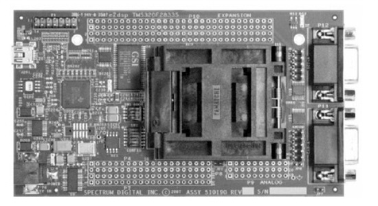
    This is the board that i'm using, the port of CAN module it's the down connector (DB9)

    Thank you

  • Hi Karol,

    Both the DB9 connectors are can transceivers? If that is the case then 1 of them must connect to ECana and the other to ECanb. Correct?

    Vivek

  • Hi Vivek

    No, the DB9 connectors one of them is CAN-A the other is SCPI. you could see this document on page 87 eCAN Block Diagram and Interface Circuit. 

    thank you

    2476.tms320f28335.pdf

  • Hi Karol,

    Just wanted some further clarification. So even though there are 2 CAN moduled in TMS320F28335, only 1 is accessible on the DB9 connector. If it's a development board i'm assuming there is some switch that selects between SCI/CAN function on the DB9.

    Vivek

  • Hi Karol,

    Found it. Found the links to the ezDSP board schematics and technical refernce guide. Here's the link in case you don't have i.

    http://c2000.spectrumdigital.com/ezf28335/

    So as i see it. There are two Can tranceivers on the board.

    ECana comes on  (P11) : DB9 Connector

    ECanb comes on (J11) : Header

    So here's what you need to do.

    Step1: Link the DSP outputs to the transceiver using SW2. That is SW2, Position 1-4 must be in on position. Refer to pg 2-25 of http://c2000.spectrumdigital.com/ezf28335/docs/ezdspf28335c_techref.pdf

    Step 2: Connect the CANH and CANL on P11 and J11.

                  P11-7 to J11-4

                  P11-2 to J11-3

    Step 3: Build and flash the example i attached earlier and watch variables like i mentioned earlier on this thread.

    Hope all this helps.

    Vivek.

  • Hi Vivek

    Thank you for the response, excuse me for make a lot of questions. But according to technical reference guide 

    The eZdsp F28335 has a 9 Pin female D-connector which brings out the CANA transmit and receive signals, This CAN interface uses the SN65HVD235 CAN driver this means that i need to buy a SN65HVD235 and connect to connector DB9.  

    And  The CANB signals are routed through the SN65HVD235 CAN driver to a 5 x 2 double  row header, J11 this means that i need buy too a SN65HVD235 and connect to connector DB9.  

    But i don´t understand why i have to connect 

                  P11-7 to J11-4

                  P11-2 to J11-3

    On my network i have de connector DB9 connected a new circuit with a transceiver and the transceiver connected  to wire (BUS wire belden9841), i don't know how connect two nodes, could you tell if two nodes are differents dsp or for one node i need one DSP and for the other need another

    Thank you so much

  • Hi Karol,

    First thing you got to understand is that there are 2 can modules in  each TMS320F28335, eCana and eCanb. These two can modules are independent to each other and they can b connected in single can bus. So instead of using 2 dsps to connect to each other, you can create a CAN network using 1 DSP only. All you have to do is connect CANHB to CANHA and CANLB to CANLA.

    Now CANHA and CANLA comes out in P11.

    CANHB and CANLB come out in J11. 

    That is why you can make the connections like i said in my earlier post. This will completely avoid another dsp. Your initial testing and understanding of CAN will be easier with just 1 dsp to program.

    Vivek

  • hi vivek! 

    thank you for your response, i have another question, if i make the connections like you said it is like  i'll have two nodes on the network?

    Thank you

    Karol

  • Hi vivek!

    i was analizing you older post with the documents (Appendix A eZdspTMF28335 Schematics and techical reference) and according with your suggestion i connected  CANH and CANL on P11 and J11 like that:

                  P11-7 to J11-4

                  P11-2 to J11-3

    But according to Appendix A eZdspTMF28335 Schematics page A-8 Pin 11-7 and P11-2 must to be connected to CAN transceiver, the same for J11-4 and J11-3. If I both connected  where i'll put the CAN transceiver?

    Thank you so much for your response, i appreciate so much your help

  • Hi Karol,

    Please take a closer look at the schematics, the transceivers are already there on the board. One is connected to J11 and other to P11.

    Vivek

  • Hi Vivek

    I told you that i was looking the schematics, nevertheless i was testing my network with two dsp for using only module CANA. i load the routine on 1 dsp and disconnect of the pc, and i load the routine on the other dsp i was looking the registers on watch window. each dsp is connected to a transceiver but my question is how i sent a message on the network?

    i have a CAN interface of grid connect that work with hyperterminal these is connected to a wire belden 9841 but when i send a message the network doesn't receive a message.

    thank you 

    Karol