Other Parts Discussed in Thread: TMS320F28335, CONTROLSUITE
Hi!
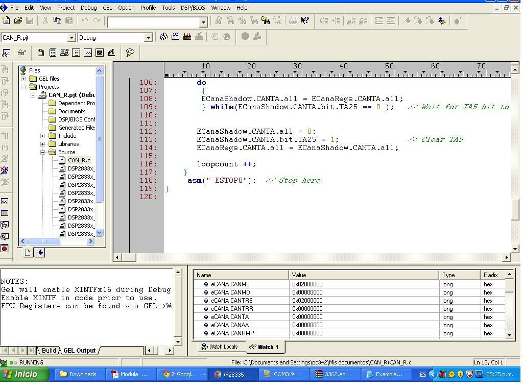
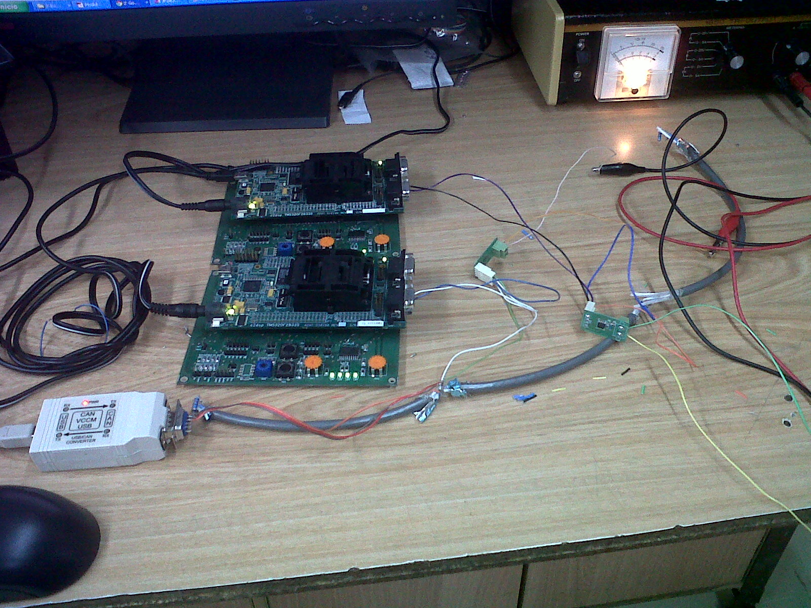
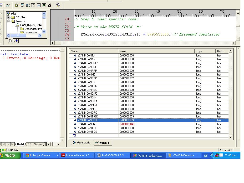
I have to do a network CAN with TMS320F28335, first of all i programming the module CAN on code composer studio, for use CANA. Then i used another DSP and programming the same code on the other. This i did for have two nodes on the network.
Then i check the schematics on this page http://c2000.spectrumdigital.com/ezf28335/docs/ezdspf28335_schem.pdf, but my question if it is necessary put the resistor before the JP7?
if i connected each DSP to transceiver and this is connected to a pair of lines (wire belden 9841) it is posiible to send and receive the messages.
Please help me
Thank you
These is my routine
#include "DSP2833x_device.h"
// external function prototypes
extern void InitSysCtrl(void);
extern void InitPieCtrl(void);
extern void InitPieVectTable(void);
extern void InitCpuTimers(void);
extern void InitECan(void);
extern void ConfigCpuTimer(struct CPUTIMER_VARS *, float, float);

void Gpio_select(void);
interrupt void cpu_timer0_isr(void);


void main (void)
{

int counter=0;
struct ECAN_REGS ECanbShadow; //used as a local copy of the original CAN registers
InitSysCtrl(); // Initialize the CPU

EALLOW; // Enable EALLOW protected register access, is possible to write freely in this protected registers
SysCtrlRegs.WDKEY = 0x55;
SysCtrlRegs.WDKEY = 0xAA;
EDIS;


Gpio_select(); // function GPIO30 as TX and GPIO31 as RX

InitECan(); // initialization CAN module


//preparation the transmit mailbox
ECanbMboxes.MBOX5.MSGID.all     = 0x10000000; //identifier
ECanbMboxes.MBOX5.MSGID.bit.IDE = 1;  //extended identifier

// configure mailbox 5

ECanbShadow.CANMD.all = ECanbRegs.CANMD.all;
ECanbShadow.CANMD.bit.MD5 = 0;
ECanbRegs.CANMD.all = ECanbShadow.CANMD.all;

// enable mailbox #5

ECanbShadow.CANME.all = ECanbRegs.CANME.all;
ECanbShadow.CANME.bit.ME5 = 1;
ECanbRegs.CANME.all = ECanbShadow.CANME.all;

// Data Length Code Field (DLC) in Message Control Register

ECanbMboxes.MBOX5.MSGCTRL.all = 0; //clear all reiaming bits of this register
ECanbMboxes.MBOX5.MSGCTRL.bit.DLC = 1;

ECanbMboxes.MBOX5.MSGID.all     = 0x10000000;	// message identifier
ECanbMboxes.MBOX5.MSGID.bit.IDE = 1;  // Extended Identifier

InitPieCtrl();		// basic setup of PIE table; from DSP2833x_PieCtrl.c

InitPieVectTable();	// default ISR's in PIE

	EALLOW;
	PieVectTable.TINT0 = &cpu_timer0_isr;
	EDIS;

	InitCpuTimers();	// basic setup CPU Timer0, 1 and 2

	ConfigCpuTimer(&CpuTimer0,150,100000);

	PieCtrlRegs.PIEIER1.bit.INTx7 = 1;

	IER |=1;

	EINT;
	ERTM;

	CpuTimer0Regs.TCR.bit.TSS = 0;	// start timer0


ECanbMboxes.MBOX5.MDL.byte.BYTE0=counter;
ECanbShadow.CANTRS.all=0;
ECanbShadow.CANTRS.bit.TRS5=1; // set the TRS(n) bit to 1 to start the transmission
ECanbShadow.CANTRS.all=ECanbShadow.CANTRS.all;

while(1)
	{
	  		while(CpuTimer0.InterruptCount < 10)	// wait for 10*100 milliseconds
			{
				EALLOW;
				SysCtrlRegs.WDKEY = 0xAA;	// service WD #2
				EDIS;
			}
			CpuTimer0.InterruptCount = 0;

			ECanbMboxes.MBOX5.MDL.byte.BYTE0 = counter & 0x00FF ;
     		ECanbShadow.CANTRS.all = 0;
     		ECanbShadow.CANTRS.bit.TRS5 = 1;     // Set TRS for mailbox under test
     		ECanbRegs.CANTRS.all = ECanbShadow.CANTRS.all;

			while(ECanbRegs.CANTA.bit.TA5 == 0 ) // Wait for TA5 bit to be set.
     		{
				EALLOW;
				SysCtrlRegs.WDKEY = 0xAA;				// Service watchdog #2
				EDIS;
     		}

	     	ECanbShadow.CANTA.all = 0;
	     	ECanbShadow.CANTA.bit.TA5 = 1;     	 // Clear Transmit Acknowledge #5
	     	ECanbRegs.CANTA.all = ECanbShadow.CANTA.all;

			counter++;
			GpioDataRegs.GPBTOGGLE.bit.GPIO34 = 1;		// toggle red LED LD3 @ 28335CC

     }


}

void Gpio_select(void)
{

    EALLOW;
	GpioCtrlRegs.GPAMUX1.all = 0;		// GPIO15 ... GPIO0 = General Puropse I/O
	GpioCtrlRegs.GPAMUX2.all = 0;		// GPIO31 ... GPIO16 = General Purpose I/O

	GpioCtrlRegs.GPAMUX2.bit.GPIO30 = 1;	// Enable pull-up for GPIO30  (CANRXA)
	GpioCtrlRegs.GPAMUX2.bit.GPIO31 = 1;	// Enable pull-up for GPIO31  (CANTXA)

	GpioCtrlRegs.GPBMUX1.all = 0;		// GPIO47 ... GPIO32 = General Purpose I/O
	GpioCtrlRegs.GPBMUX2.all = 0;		// GPIO63 ... GPIO48 = General Purpose I/O
	GpioCtrlRegs.GPCMUX1.all = 0;		// GPIO79 ... GPIO64 = General Purpose I/O
	GpioCtrlRegs.GPCMUX2.all = 0;		// GPIO87 ... GPIO80 = General Purpose I/O

	GpioCtrlRegs.GPADIR.all = 0;
	GpioCtrlRegs.GPADIR.bit.GPIO9 = 1;	// peripheral explorer: LED LD1 at GPIO9
	GpioCtrlRegs.GPADIR.bit.GPIO11 = 1;	// peripheral explorer: LED LD2 at GPIO11

	GpioCtrlRegs.GPBDIR.all = 0;		// GPIO63-32 as inputs
	GpioCtrlRegs.GPBDIR.bit.GPIO34 = 1;	// peripheral explorer: LED LD3 at GPIO34
	GpioCtrlRegs.GPBDIR.bit.GPIO49 = 1; // peripheral explorer: LED LD4 at GPIO49
	GpioCtrlRegs.GPCDIR.all = 0;		// GPIO87-64 as inputs

	EDIS;
}

interrupt void cpu_timer0_isr(void)
{
	CpuTimer0.InterruptCount++;
	EALLOW;
	SysCtrlRegs.WDKEY = 0x55;	// service WD #1
	EDIS;
	PieCtrlRegs.PIEACK.all = PIEACK_GROUP1;
}