This thread has been locked.

If you have a related question, please click the "Ask a related question" button in the top right corner. The newly created question will be automatically linked to this question.

serial communication piccolo F28069 control stick

Other Parts Discussed in Thread: CONTROLSUITE, MAX232

 hai

         i want to implement the serial communication on piccolo control stick F28069.i want some of the details.

                   which gpio pins should be configured ?????

                   what are the corresponding pins on the control stick .?

                   Any example projects regarding serial communication on piccolo control stick????

                     please help me........

thanks in advance.................

  • chakravarthi g said:
    i want to implement the serial communication

    What "serial communication" ?

    There are many different types of serial communication; eg,

    • SPI
    • I2C
    • USB
    • RS232

    chakravarthi g said:
    which gpio pins should be configured

    Whichever pins carry the required interface!

    Look at the device datasheet for details.

    chakravarthi g said:
    what are the corresponding pins on the control stick .?

    Look at the stick documentation - including the schematics - for details.

    chakravarthi g said:
    Any example projects regarding serial communication on piccolo control stick????

    http://www.ti.com/mcu/docs/mcuprodtoolsw.tsp?sectionId=95&tabId=2884&familyId=919&toolTypeId=1

  •  sorry i require sci.i have tried sci_echoback project provided in the device support examples,in that GPIO 27 &GPIO28 pins are used and those pins are not available on the control stick.can you please say which pins should i use for that on the control stick.

  • Andy Neil said:

    Look at the stick documentation - including the schematics - for details.

  • thanks i have seen but not available for gpio 28,29 .it is just mentioned thats all...pls help me.

  • Control Stick 28069 allows SCI-A  access, through GPIO7 and GPIO12, the 7 and 8 pins on the control stick

    Modify the SCI init functions in the examples to use GPIO7 and GPIO12 for TX and RX instead of GPIO28 and GPIO29,

    follow the instructions given in the example code to do this

  • thank u......i have alredy done it.in the function initgpio() i think i uncommented the gpio7,12 and commented the gpio 28,29& saved. i connected pin 7(gpio 7) on control stick which is reception to the rs232 pin no 3.and pin 8(gpio12) on control stick  which is transmission to the rs232 pin no 2.and pin no 32(gnd) on control stick to the pin no 5 in the rs232.i have debugged the program but northing displayed in the other computer.i have used the same hyperterminal as specified in the program begining.pls help me to execute this example.

  • SCI communication on controlStick 28069

    I had checked the SCI-A through pins GPIO7 and GPIO12 on the controlStick and it is working well, however for reference i have listed the procedure i follwed

    1. Import the program ..\ti\controlSUITE\device_support\f2806x\v110\F2806x_examples\scia_loopback
    2. commented the GPIO28 and GPIO29 lines and uncommented GPIO7 and GPIO12 lines as per the guidelines, this is to ensure the later pins are to be selected for the SCI-A communications
    3. Pins 7 and 8 on controlStick are shorted with a jumper (tx with rx for loop back test)
    4. Added the variables  SendChar and ReceivedChar to watch window
    5. run the program and halted to see the status, to see that send character is eual to received character
    So, with that it is understood SCI-A is accessible through GPIO7 and GPIO12 in controlStick. 
  • thanks,what you said is correct i agree .but the example you executed is an internal loop program.even though you didnt shorted the pins the result can be obtained.pin 8,7 are correct for sci.but the example i am executing is echoback same path with folder name sci_echoback.in this example transmitted thing should me displayed in the other computer hyper teminal through serial port.please see and help me.i have tried  for gpio 7,12 i.e., 7,8 on control stick.i connected these to 2,3 on the db9 cable(rs232).and also both the grounds.but northing is displayed ..

  • yes, the loop back is internally shorted by the register setting, this you can change in the init function

     SciaRegs.SCICCR.bit.LOOPBKENA =1; // Enable loop back

    if you are not setting this bit, the internal short will not happen and then you can test whether the SCI-A pins are working are not, i have tested this and it is working only when there is jumper between the GPIO7 and GPIO12, 

    ensure the below modification to make the echoback example program work in the function scia_echoback_init()

    SciaRegs.SCIHBAUD =0x0000; // 9600 baud @LSPCLK = 20MHz (80 MHz SYSCLK).
    SciaRegs.SCILBAUD =0x0103;

    since the SCILBAUD is a 8 bit value it cannot have a 12 bit value as assigned above, so modify it to 

     SciaRegs.SCIHBAUD =0x01; // 9600 baud @LSPCLK = 20MHz (80 MHz SYSCLK).
    SciaRegs.SCILBAUD =0x03;

    with the above change i had tested the echoback example and i was able to receive the characters in the hyperterminal

  • thanks a lot for ur help.i am running out of license.what is the cost of the license of css.csn you please inform me.

  • Hi Community,

    we also had the problem that we can't test the sci_echoback example on the TI controlSTICK.

    We tried the new Version V135 and find out that this includes a bug!

    To make sure the example will run correctly check the following things:

    The PLLCR settings in the file F2806x_Example.h. This was set in V135 by DSP28PLL and the DSP28_DIVSEL to

    #define DSP28_DIVSEL   2 // Enable /2 for SYSCLKOUT
    #define DSP28_PLLCR   18  // Uncomment for 90 MHz devices [90 MHz = (10MHz * 18)/2]

    BUT the void scia_echoback_init() function has been set to the wrong baud rate in the file Example_2806x_Sci_Echoback.c

    SciaRegs.SCIHBAUD    =0x0001;  // 9600 baud @LSPCLK = 20MHz (80 MHz SYSCLK).
    SciaRegs.SCILBAUD    =0x0003;

    and this was WRONG and you can't receive correct characters over the sci.

    In this case you can configure the PLLCR register to fit 80 MHz or calculate the new baudrate for 9600 baud @LSPCLK = 22.5 MHz (90 MHz SYSCLK)

    SciaRegs.SCIHBAUD    =0x0001;  // 9600 baud @LSPCLK = 22.5MHz (90 MHz SYSCLK).
    SciaRegs.SCILBAUD    =0x0023;

    Hope this helps.

    Maybe anybody at TI will fix this for the new Version?!

    Kind regards

    PS: There was no need to set a jumper between GPIO7 and GPIO12 on the controlSTICK the example works with correct PLLCR/SYSCLK and baud rate

  • Hi Pascal,

    I ran into the same problem using the F28069 Experimenter Board.

    Thanks a lot for the post!

    PS: Yes, it would be great if TI could fix this...

    Best,

    Gustav

  • Hi everybody,

    I'm working on the TMS320C2000 Development Tools and try to test the sci_echoback example on the TI controlSTICK F28069. Everything seems ok in the code but I can't receive or transmit anything to/from an Hyperterminal. I check the COM configuration and registers but I don't find where the problem is.


    Could someone help me?

    Thanks,


    Christopher

    Ps: I'm working on ccsv4 and Windows 8

  • Hello Christopher,

    I suggest you to post the new thread since this thread already has verified mark.

    About your SCI, are you sure you choose the correct COM?

    You should choose COM port that has name USB Serial Port (COMxx) that you can see in Device Manager.

    Best regards,

    Maria

  • Hello Maria,

    Thanks for your reply. 

    Yes I'm sure that I choose the correct COM with the correct Baudrate. But nothing is receive or transmit...

    Best regards,

    Christopher

  • Yes I'm sure that I choose the correct COM with the correct Baudrate. But nothing is receive or transmit...

    You need a level shifter IC for communication with PC! MAX232 is one example.

    Regards,

    Gautam

  • Which example that you refer to?

    Please try the latest version of example C:\ti\controlSUITE\device_support\f2806x\v136\F2806x_examples_ccsv5\sci_echoback

    @Gautam: Per schematic of F28069 ControlStick, there is FT2232 and RX-TX are connected there. So I think the SCI example should work using this ControlStick without additional hardware. Let's see.

    Best regards,

    Maria

  • I use the V120 version. The V136 version doesn't change anything. There are no data receive/transmit in the Hyperterminal.

    Best regards,

    Christopher

  • @Maria: I guess he COM port through USB is not getting detected and hence as a quick solution MAX232 would do the job. This might be due to improper driver loading.

    @Christopher: Here's the doc which explains the procedure: 1258.SCI_ECHOBACK.pdf

    Regards,

    Gautam

  • Gautam,

    Thanks for the doc. I still followed these intructions but with no more results.

    Regards,

    Christopher

  • Hello Christopher,

    Can you check whether the SCI pins (TX-RX) connected to FT2232 are GPIO28/GPIO29 or other GPIOs (7/12)?

    Please refer to the schematic of ControlStick and pin diagram of F28069 to find which pins they are.

    Best regards,

    Maria

  • Hello Maria,

    The SCI pins connected to FT2232 are GPIO28(RX) ans GPIO29(TX). I checked the code and the configuration is correct.

    Best regards,

    Christopher

  • Hello Christopher,

    Then I am not sure what's wrong with your ControlStick.

    1. Are you sure it doesn't send anything?When you type some characters, it should response like this (in this example below, I type 'a' and 'b').

    2. Can you use Terminal from CCS (instead of Hyperterminal) and set it to the correct setting? (in my case, the COM port is COM13 that you can see in the picture above)

    3. Can you send us the snapshot of your Device Manager that shows the COM ports? Also make sure that no other USB COM port connected except your ControlStick.

    4. When you stop your debugger, in which line it stops (please keep using the latest ControlSuite example for this test)?

    5. In another case, you can use GPIO12 and GPIO7 and connect to MAX232 to establish SCI communication, just like Gautam recommended previously.

    Best regards,

    Maria

  • Hello Maria,

    Thanks for your reply.

    1/2. Yes, I'm sure it doesn't send anything. I also tried with the Terminal from CCS but there is no change. 

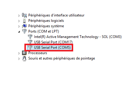
    3. Here is the snapshot of my Device Manager:

    The COM5 is the COM that I use to send and receive data to/from the Hyperterminal. The COM17 is the one of the USB/JTAG emulator.

    4. When I stop the debugger, the program stops in this line:

    So it's waiting for an input character.

    5. Yes it could be a possibility but I would like to be able to do this with the first method.

    Also I don't use a null modem RS232 cable. Do you think it could be a problem?

    Best Regards,

    Christopher

  • Christopher Wawrzyniak said:
    COM17

    Try with this COM port.

    It should be appeared only one USB Serial Port. So I don't know why it appears two (if your already make sure that there is no other USB serial connected to your PC).

    Best regards,

    Maria

  • Maria,

    In fact, there are two USB ports used: COM5 for serial communication and COM17 to flash the card with the USB/JTAG emulator. Should I take off the USB from USB/JTAG emulator?

    Best Regards,

    Christopher

  • You may try it and let us know what the result is.

    Best regards,

    Maria

  • Well, I tried to take off the USB from USB/JTAG emulator but that didn't change anything. 

    Best regards,

    Christopher

  • Hello Maria,

    I found the solution! It was a problem of cable. I didn't use a null modem cable so I didn't have access to data. Now everything is correct.

    Thanks for your help!

    Best regards,

    Christopher

  • I found the solution! It was a problem of cable. I didn't use a null modem cable so I didn't have access to data. Now everything is correct.

    Ahhh! Good, good that you were able to spot the issue.

    Goodluck & Regards,

    Gautam

  • Christopher Wawrzyniak said:
    I found the solution! It was a problem of cable. I didn't use a null modem cable so I didn't have access to data. Now everything is correct.

    That's great you found it (because I was already lack of advice what to check :) )

    Good luck and cheers!

    Best regards,

    Maria