This thread has been locked.

If you have a related question, please click the "Ask a related question" button in the top right corner. The newly created question will be automatically linked to this question.

C2000 LaunchPad LED BoosterPack Capacitive Touch Demo

Other Parts Discussed in Thread: CONTROLSUITE

HI,

I am trying to do the C2000 hardware Capactive touch demo on the LED BoosterPack.

Issue is it appears to have conflicting directions on the documentation (neither work after I loaded the demo code in ControlSuite called,

File: f2802x_examples/LED_Boost_CapTouch/LED_Boost_CapTouch_Main.c


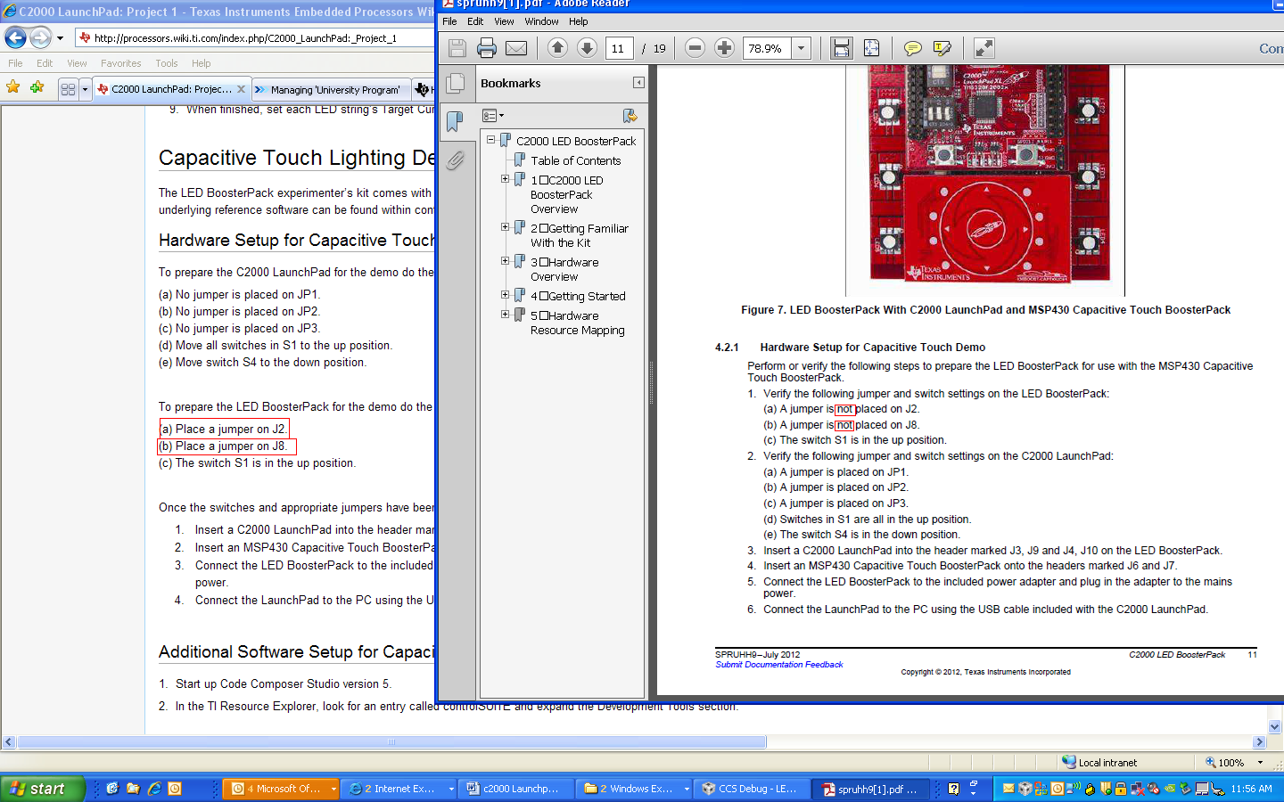
The User Guide tells me not to have jumpers on the LaunchPad, but the Wiki has the reverse.

The User Guide
4.2.1 Hardware Setup for Capacitive Touch Demo

Perform or verify the following steps to prepare the LED BoosterPack for use with the MSP430 Capacitive Touch BoosterPack.

1. Verify the following jumper and switch settings on the LED BoosterPack:
(a) A jumper is not placed on J2.
(b) A jumper is not placed on J8.
(c) The switch S1 is in the up position.

2. Verify the following jumper and switch settings on the C2000 LaunchPad:
(a) A jumper is placed on JP1.
(b) A jumper is placed on JP2.
(c) A jumper is placed on JP3.
(d) Switches in S1 are all in the up position.
(e) The switch S4 is in the down position.

3. Insert a C2000 LaunchPad into the header marked J3, J9 and J4, J10 on the LED BoosterPack.

4. Insert an MSP430 Capacitive Touch BoosterPack onto the headers marked J6 and J7.

5. Connect the LED BoosterPack to the included power adapter and plug in the adapter to the mains power.

6. Connect the LaunchPad to the PC using the USB cable included with the C2000 LaunchPad.


the Wiki 
Hardware Setup for Capacitive Touch Lighting Demo

To prepare the C2000 LaunchPad for the demo do the following:
(a) No jumper is placed on JP1.
(b) No jumper is placed on JP2.
(c) No jumper is placed on JP3.
(d) Move all switches in S1 to the up position.
(e) Move switch S4 to the down position.

To prepare the LED BoosterPack for the demo do the following:
(a) Place a jumper on J2.
(b) Place a jumper on J8.
(c) The switch S1 is in the up position.

Once the switches and appropriate jumpers have been placed on the LED BoosterPack and the C2000 LaunchPad do the following:

  1. Insert a C2000 LaunchPad into the header marked J3, J9 and J4, J10 on the LED BoosterPack.
  2. Insert an MSP430 Capacitive Touch BoosterPack onto the headers marked J6 and J7.
  3. Connect the LED BoosterPack to the included power adapter and plug in the adapter to the mains
    power.
  4. Connect the LaunchPad to the PC using the USB cable included with the C2000 LaunchPad.


Neither one of the configurations does the Cap Touch BoosterPack light up (like it does with the MSP430 LaunchPad to let us know that it's receiving power).


Can someone confirm the correct hardware configuration for the Capactitive Lighting Demo?


  • Larissa,

    Either set of the instructions should work.  The instructions in the user guide supply power for the 3.3V components from the USB power, while the wiki instructions power all the components using power from the wall wart.

    Can you check to see if the MSP430 is getting 3.3V?  If it isn't I suspect our CM may not have properly programmed this board.

    Trey

  • Hi Trey,

    Perhaps we need to fix the wiki and the guide?
    Both suggest plugging in the power adapter.

    However, I still can't seem to get either set up to work.

    The Cap Touch Demo on the MSP430 LaunchPad:
    using the G2452 chip on instead of the onboard G2553 that shipped with the LaunchPad.
    If you see, as soon as I plug it in there is a light to let me know that it's recieving power.

    I played a little more around with the C2000 LaunchPad and BoosterPack.
    I got the configuration to work with jumpers on J2J8 on the BoosterPack and ones on JP3 and JP2 on the C2000 LaunchPad  over USB Power only- Below Video (apologies for the iphone, one handed video)

    Not sure if this is okay, because although the captouch then worked the USB Power got hot.

    Still not sure how to get this demo working, but I do think there is an issue with the documentation.

  • Okay, after spending a lot of time on this on my own, I did get it to work. 

    First, the LaunchPad has to have the code on it before connecting it to the BoosterPack (seems simple, but just reading the directions I didn't get this). 
    To get the code loaded on the LaunchPad (without the boosterpack)
    We need jumpers on J1, J2 and J3
    S1 the switches to be up, up, down
    and S4 to be down.

    I had one minor issue where the the debugger didn't connect (not sure what happened). It worked when I moved the last switch to the up position to have S1 be up, up and up. 

    Once the LaunchPad had the code then I got the BoosterPack ready. 

    No jumpers on J2 and J8 (on the LED Boosterpack). 
    The large switch in the up position. 

    I plugged in the Capacitive Touch BoosterPack.
    Then plugged in the LaunchPad and had
    S4 Down
    S1, Up, Up and Up.

    Then I connected the USB cable to the LaunchPad. The Capacitive Touch board lit up.
    Then I took the Power Supply and plugged the power supply into the BoosterPack board.

    When I thought it wasn't working it suddenly started to cycle through the colours. For three or four cycles, it would turn off then cycle through (not sure if this is due to the code on the cap touch BoosterPack).

    Then, it started to work all of the time by tapping the center cap touch button, then scrolling.

    I'm a bit confused as to the jumper configurations being different or why switching them works, perhaps this is an isolated case, but now it does work.


  • Larissa,

    Sorry to hear you had trouble.  I'm going to comment on your findings inline below:

    First, the LaunchPad has to have the code on it before connecting it to the BoosterPack (seems simple, but just reading the directions I didn't get this). 
    To get the code loaded on the LaunchPad (without the boosterpack)
    We need jumpers on J1, J2 and J3
    S1 the switches to be up, up, down
    and S4 to be down.

    >> The Launchpad should be able to be programmed irregardless of if the boosterpack is connected.  To program the Launchpad without a boosterpack (i.e. power is supplied from USB) JP1 and JP2 must be jumpered...JP3 DOES NOT need to be jumpered.  The only thing JP3 does is supply 5V to one of the boosterpack header pins. S4 is irrelevant for programming, and the S1 switches MUST BE up, up, up in order for the debugger to be able to connect and program the target device.  If the S1 switches are up, up, down you will be unable to connect and program the target device.

    I had one minor issue where the the debugger didn't connect (not sure what happened). It worked when I moved the last switch to the up position to have S1 be up, up and up. 

    >>Exactly! S1 position 3 selectively connect the TRSTn signal to the emulator.  This is basically used by the chip to tell if it should go ahead and try to boot standalone or wait for a debugger connection.  IF S1 SWITCH 3 IS DOWN THE DEBUGGER WILL NOT CONNECT.

    Once the LaunchPad had the code then I got the BoosterPack ready. 

    No jumpers on J2 and J8 (on the LED Boosterpack). 
    The large switch in the up position. 

    >> No jumpers are required on J2 and J8 if jumpers are placed on JP1, JP2, and JP3 on the LaunchPad.  In this scenario power is supplied to all the 3.3V components with power from USB.  Another valid configuration would be to NOT place jumpers on JP1, JP2, and JP3 and TO place jumpers on J2 and J8.  In this scenario power for both the LaunchPad and BoosterPack would be supplied by the power jack on the boosterpack.

    >>The big switch on the boosterpack determines if the MSP430 UART is connected to the BoosterPack connector or not. This is there to prevent contention between all of the UARTs that are connected to the boosterpack pins.

    I plugged in the Capacitive Touch BoosterPack.
    Then plugged in the LaunchPad and had
    S4 Down
    S1, Up, Up and Up.

    >> Good, this allows the debugger to connect and allows the Piccolo device to talk to the MSP430 over its UART.  This also prevents the FTDI's UART from contending with the other two UARTs on these pins.

    Then I connected the USB cable to the LaunchPad. The Capacitive Touch board lit up.
    Then I took the Power Supply and plugged the power supply into the BoosterPack board.

    When I thought it wasn't working it suddenly started to cycle through the colours. For three or four cycles, it would turn off then cycle through (not sure if this is due to the code on the cap touch BoosterPack).

    Then, it started to work all of the time by tapping the center cap touch button, then scrolling.

    >>Lights should initially turn on after a double click of the center touch button.  Scrolling with then change the color. Any subsequent single clicks of the center touch button will turn the LEDs off or on depending on the current state.

    I'm a bit confused as to the jumper configurations being different or why switching them works, perhaps this is an isolated case, but now it does work.

    >>Glad to hear it is working for you now.  Try looking at the schematic in controlSUITE.  I think it will make clear what all the jumpers do.

    Trey