Hi,
I am working on TMS320F2812 CAN module i made a sample program for CAN reception which my TMS board should receive.
my TMS board is interfaced with external tranceiver from micorchip MCP2551 along with voltage level shifters to suit to 3.3v of TMS CAN module ( interface board is also attached in PDF format)
I am using a baud rate of 250 kbps. i am using header files prodived by TI .
I am attaching CAN initialization file and my main file for refernce.
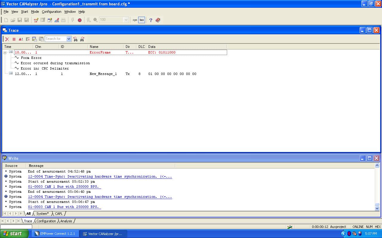
I am trying to receive CAN standard message ( message ID: 0x0001) which is transmitted via vector CANalyzer tool, but i get Form error and messages transmission gets stopped (after some time) and no more communication happens ( screenshot from CANalyzer is also attached).
Before the communication stops what ever data was transmitted by CANalyzer tool TMS reads and shows in watch window but error persists and CAN nodes stops participating in communication and no more tranmission from CANalyzer tool (here CANalyzer is transmit node).
I donot know what is causing this form error, i read about error but donot know how to fix it.
please can any one help me?. what could be wrong in my code?.
Thanks in advance,
Sangeetha
void InitECan(void)
{

/* Create a shadow register structure for the CAN control registers. This is
 needed, since only 32-bit access is allowed to these registers. 16-bit access
 to these registers could potentially corrupt the register contents or return
 false data. This is especially true while writing to/reading from a bit
 (or group of bits) among bits 16 - 31 */

	struct ECAN_REGS ECanaShadow;

	asm("  EALLOW");

/* Configure eCAN pins for CAN operation using GPIO regs*/

	GpioMuxRegs.GPFMUX.bit.CANTXA_GPIOF6 = 1;
	GpioMuxRegs.GPFMUX.bit.CANRXA_GPIOF7 = 1;

	// eCAN control registers require 32-bit access.
    // If you want to write to a single bit, the compiler may break this
    // access into a 16-bit access.  One solution, that is presented here,
    // is to use a shadow register to force the 32-bit access.

    // Read the entire register into a shadow register.  This access
    // will be 32-bits.  Change the desired bit and copy the value back
    // to the eCAN register with a 32-bit write.

/* Configure eCAN RX and TX pins for CAN operation using eCAN regs*/

    ECanaShadow.CANTIOC.all = ECanaRegs.CANTIOC.all;
    ECanaShadow.CANTIOC.bit.TXFUNC = 1;
    ECanaRegs.CANTIOC.all = ECanaShadow.CANTIOC.all;

    ECanaShadow.CANRIOC.all = ECanaRegs.CANRIOC.all;
    ECanaShadow.CANRIOC.bit.RXFUNC = 1;
    ECanaRegs.CANRIOC.all = ECanaShadow.CANRIOC.all;

/* Configure eCAN for HECC mode - (reqd to access mailboxes 16 thru 31) */
// HECC mode also enables time-stamping feature

	ECanaShadow.CANMC.all = ECanaRegs.CANMC.all;
	ECanaShadow.CANMC.bit.SCB = 1;
	ECanaRegs.CANMC.all = ECanaShadow.CANMC.all;

/* Initialize all bits of 'Master Control Field' to zero */
// Some bits of MSGCTRL register may come up in an unknown state. For proper operation,
// all bits (including reserved bits) of MSGCTRL must be initialized to zero

    ECanaMboxes.MBOX0.MSGCTRL.all = 0x00000000;
    ECanaMboxes.MBOX1.MSGCTRL.all = 0x00000000;
    ECanaMboxes.MBOX2.MSGCTRL.all = 0x00000000;
    ECanaMboxes.MBOX3.MSGCTRL.all = 0x00000000;
    ECanaMboxes.MBOX4.MSGCTRL.all = 0x00000000;
    ECanaMboxes.MBOX5.MSGCTRL.all = 0x00000000;
    ECanaMboxes.MBOX6.MSGCTRL.all = 0x00000000;
    ECanaMboxes.MBOX7.MSGCTRL.all = 0x00000000;
    ECanaMboxes.MBOX8.MSGCTRL.all = 0x00000000;
    ECanaMboxes.MBOX9.MSGCTRL.all = 0x00000000;
    ECanaMboxes.MBOX10.MSGCTRL.all = 0x00000000;
    ECanaMboxes.MBOX11.MSGCTRL.all = 0x00000000;
    ECanaMboxes.MBOX12.MSGCTRL.all = 0x00000000;
    ECanaMboxes.MBOX13.MSGCTRL.all = 0x00000000;
    ECanaMboxes.MBOX14.MSGCTRL.all = 0x00000000;
    ECanaMboxes.MBOX15.MSGCTRL.all = 0x00000000;
    ECanaMboxes.MBOX16.MSGCTRL.all = 0x00000000;
    ECanaMboxes.MBOX17.MSGCTRL.all = 0x00000000;
    ECanaMboxes.MBOX18.MSGCTRL.all = 0x00000000;
    ECanaMboxes.MBOX19.MSGCTRL.all = 0x00000000;
    ECanaMboxes.MBOX20.MSGCTRL.all = 0x00000000;
    ECanaMboxes.MBOX21.MSGCTRL.all = 0x00000000;
    ECanaMboxes.MBOX22.MSGCTRL.all = 0x00000000;
    ECanaMboxes.MBOX23.MSGCTRL.all = 0x00000000;
    ECanaMboxes.MBOX24.MSGCTRL.all = 0x00000000;
    ECanaMboxes.MBOX25.MSGCTRL.all = 0x00000000;
    ECanaMboxes.MBOX26.MSGCTRL.all = 0x00000000;
    ECanaMboxes.MBOX27.MSGCTRL.all = 0x00000000;
    ECanaMboxes.MBOX28.MSGCTRL.all = 0x00000000;
    ECanaMboxes.MBOX29.MSGCTRL.all = 0x00000000;
    ECanaMboxes.MBOX30.MSGCTRL.all = 0x00000000;
    ECanaMboxes.MBOX31.MSGCTRL.all = 0x00000000;

// TAn, RMPn, GIFn bits are all zero upon reset and are cleared again
// as a matter of precaution.

/* Clear all TAn bits */

	ECanaRegs.CANTA.all	= 0xFFFFFFFF;

/* Clear all RMPn bits */

	ECanaRegs.CANRMP.all = 0xFFFFFFFF;

/* Clear all interrupt flag bits */

	ECanaRegs.CANGIF0.all = 0xFFFFFFFF;
	ECanaRegs.CANGIF1.all = 0xFFFFFFFF;

/* Configure bit timing parameters */

	ECanaShadow.CANMC.all = ECanaRegs.CANMC.all;
	ECanaShadow.CANMC.bit.CCR = 1 ;            		// Set CCR = 1
    ECanaRegs.CANMC.all = ECanaShadow.CANMC.all;

    ECanaShadow.CANES.all = ECanaRegs.CANES.all;

	// Wait until the CPU has been granted permission to change the configuration registers
    do
    {
      ECanaShadow.CANES.all = ECanaRegs.CANES.all;
    } while(ECanaShadow.CANES.bit.CCE!= 1 );  		// Wait for CCE bit to be set..

   /* ECanaShadow.CANBTC.all = 0;
    ECanaShadow.CANBTC.bit.BRPREG = 9;				// 1 Mbps @ 150 MHz SYSCLKOUT
    ECanaShadow.CANBTC.bit.TSEG2REG = 2;
    ECanaShadow.CANBTC.bit.TSEG1REG = 10;
    ECanaShadow.CANBTC.bit.SAM = 1;
    ECanaRegs.CANBTC.all = ECanaShadow.CANBTC.all; */

     ECanaShadow.CANBTC.all = 0;
    ECanaShadow.CANBTC.bit.BRPREG = 59;				// 250 kbps @ 150 MHz SYSCLKOUT
    ECanaShadow.CANBTC.bit.TSEG2REG = 1;
    ECanaShadow.CANBTC.bit.TSEG1REG = 6;
    ECanaShadow.CANBTC.bit.SAM = 1;
    ECanaRegs.CANBTC.all = ECanaShadow.CANBTC.all;


    ECanaShadow.CANMC.all = ECanaRegs.CANMC.all;
	ECanaShadow.CANMC.bit.CCR = 0 ;            		// Set CCR = 0
    ECanaRegs.CANMC.all = ECanaShadow.CANMC.all;

    ECanaShadow.CANES.all = ECanaRegs.CANES.all;

	// Wait until the CPU no longer has permission to change the configuration registers
    do
    {
      ECanaShadow.CANES.all = ECanaRegs.CANES.all;
    } while(ECanaShadow.CANES.bit.CCE != 0 ); 		// Wait for CCE bit to be  cleared..

/* Disable all Mailboxes */
    // Since this write is to the entire register (instead of a bit
    // field) a shadow register is not required.

 	ECanaRegs.CANME.all = 0;		// Required before writing the MSGIDs
}
#include "DSP281x_Device.h"     // DSP281x Headerfile Include File
#include "DSP281x_Examples.h"   // DSP281x Examples Include File

// Prototype statements for functions found within this file.

void mailbox_read(int16 i);

// Global variable for this example

Uint32  TestMbox1 = 0;
Uint32  TestMbox2 = 0;
Uint32  TestMbox3 = 0;


void main(void)
{
Uint16  jj=1;


   struct ECAN_REGS ECanaShadow;
   InitSysCtrl();
   DINT;
   IER = 0x0000;
   IFR = 0x0000;

    InitECan();     // Initialize the eCAN module

    ECanaMboxes.MBOX0.MSGID.all = 0x00040000;// message ID standard and message ID is "1"


    ECanaRegs.CANMD.all = 0x00000001;// mail box zero is receive mail box

                                                                                                                                                                                                                                                                                                                                                                                                                                                                           ot required.
    ECanaRegs.CANME.all = 0x00000001;// enable mailbox0


    ECanaMboxes.MBOX0.MSGCTRL.bit.DLC = 8;


    // Enable the enhanced features of the eCAN.
    EALLOW;
    ECanaShadow.CANMC.all = ECanaRegs.CANMC.all;
    ECanaShadow.CANMC.bit.STM = 0;
    ECanaRegs.CANMC.all = ECanaShadow.CANMC.all;
    EDIS;


   ECanaShadow.CANRMP.all = ECanaRegs.CANRMP.all;

   ECanaShadow.CANRMP.all= 0xFFFFFFFF;

  ECanaRegs.CANRMP.all = ECanaShadow.CANRMP.all;

    // Begin transmitting
    while(1)
    {


    	ECanaShadow.CANRMP.all = ECanaRegs.CANRMP.all;

  	  if(ECanaShadow.CANRMP.bit.RMP0==1)
	  {
	  ECanaShadow.CANRMP.bit.RMP0=1;
	   jj=0;

	   mailbox_read(jj);


	   }

	ECanaRegs.CANRMP.all = ECanaShadow.CANRMP.all;

        EALLOW;
	SysCtrlRegs.WDKEY = 0x55;
	EDIS;

    }
}

// This function reads out the contents of the indicated
// by the Mailbox number (MBXnbr).


void mailbox_read(int16 MBXnbr)
{
   volatile struct MBOX *Mailbox;
   Mailbox = &ECanaMboxes.MBOX0 + MBXnbr;
   TestMbox1 = Mailbox->MDL.all; // = 0x9555AAAn (n is the MBX number)
   TestMbox2 = Mailbox->MDH.all; // = 0x89ABCDEF (a constant)
   TestMbox3 = Mailbox->MSGID.all;// = 0x9555AAAn (n is the MBX number)

}