This thread has been locked.

If you have a related question, please click the "Ask a related question" button in the top right corner. The newly created question will be automatically linked to this question.

I2C Question

Other Parts Discussed in Thread: TMS320F28035, CONTROLSUITE, TMS320F28377D

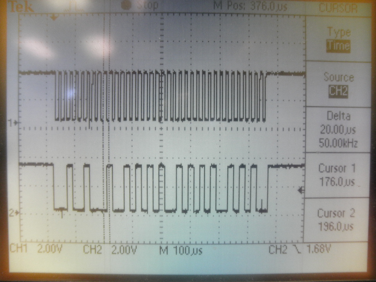
I am trying to get the I2C peripheral working on a TMS320F28035.  On my eval board, I am able to see I2C data and clock signals on my scope, but only when I2CMDR DLB (Digital Loopback is enabled) using:

I2caRegs.I2CMDR.all = 0x2E60;

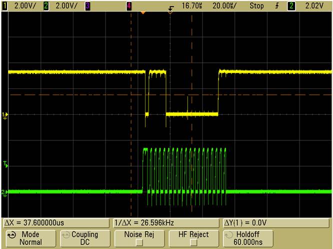
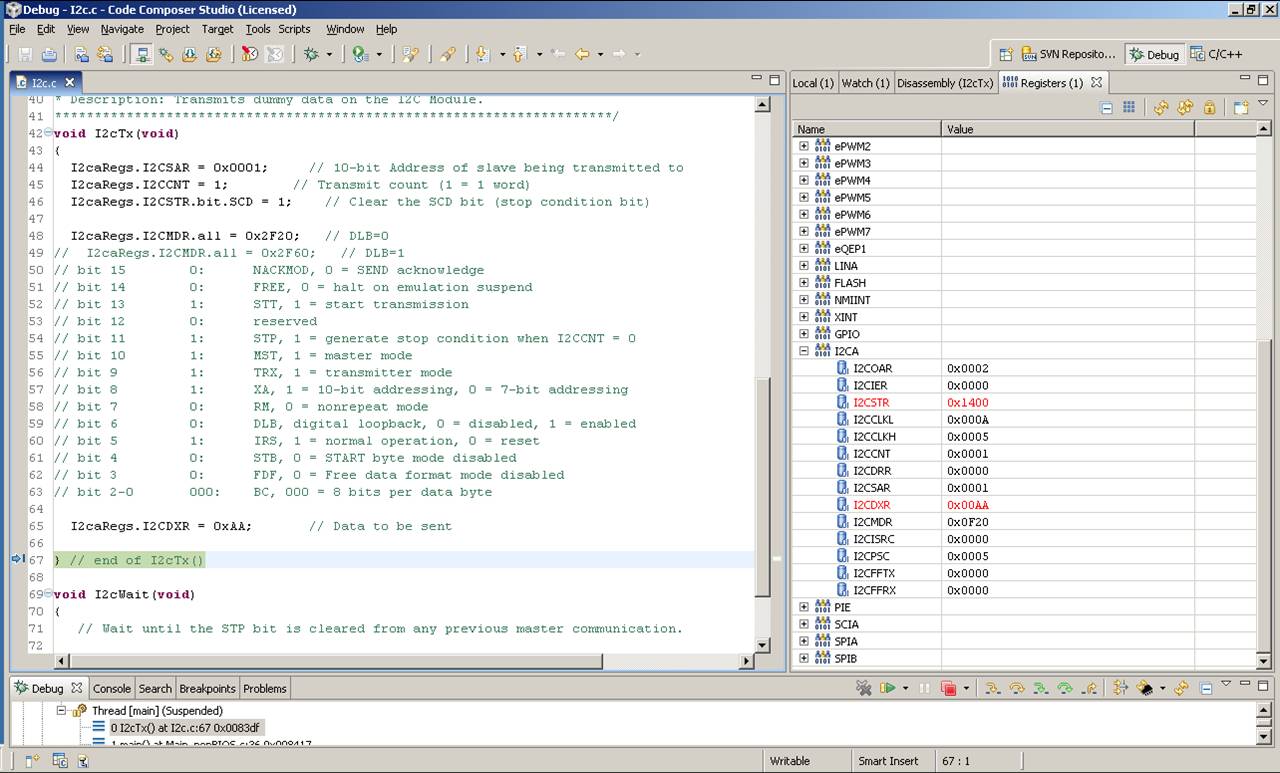
 Since I see the correct data and clock signals, I assume I have set up the peripheral correctly.  When I attempt to transmit I2C without DLB enabled using 

 I2caRegs.I2CMDR.all = 0x2E20;

I see the  data line go low, as if it is starting an I2C transmit, but then nothing else happens.

What am I missing?  Please help 


  • I2C is an open-drain bus.  Devices drive low, but hi-Z for a hi bit.  You need a pullup on the data line.  Do you have a pullup on it?

    Regards,

    David

  • Thank you very much for the quick reply.

    Yes, I do have both the I2C data and clock lines pulled to 3.3V through a  2.2k resistor.

  • I have an old CCSv3.3 project that does a simple I2C master transmit on F28335.  I have attached the project.  I'm sure you are using CCSv5, but you can still look at the code.  It is well commented and should be easy to follow.  You could make a CCSv5 project pretty easy I'm sure using these files, but hopefully just looking at the config code will be enough.  Relevant files are main_nonBIOS.c, I2C.c, and Gpio.c.  Only thing done in Gpio.c is configure the shared GPIO pins.

    Hope this helps.

    - David


  • I just realized you are using F28035, not F28335 (I mis-read it before).  Well, the I2C config code will still apply.  Same I2C peripheral.

    - David

  • Thank you for your help with this, 

    Taking a quick look, I notice your sample code has

       I2caRegs.I2CMDR.all = 0x2F60;
    // bit 6 1: DLB, 1 = digital loopback enabled

    On my test setup, I do also have the peripheral working nicely with loopback enabled.  The only change I then make is that I make DLB = 0 and then it does not work. The data line goes low as if it is properly starting the I2C xmit, but then it just stops.  The data line remains low and the clock line never starts (again it all works fine with DLB=1).  I have data and clock pulled high through a 2k. 

    I also do have

     GpioCtrlRegs.GPBMUX1.bit.GPIO32 = 1; // 1=SDAA
     GpioCtrlRegs.GPBMUX1.bit.GPIO33 = 1; // 1=SCLA  

    Is anything else required  for the pin configuration?

    Is there anything else required at the physical layer (other than pull-up resistors?)

     What would enable the peripheral to work with DLB enabled that is missing with DLB disabled?


  • Mark,

    I didn't realize the DLB bit was a 1 in my example code.  I was quickly just trying to help you, and didn't examine the code.  You were clear in your posts that stuff was working for you with DLB=1.

    OK, so I took my F28335 CCSv3.3 project that is posted previously in this thread and converted to CCSv5 just now.  It is working.  When DLB=1, the device continually transmits the data 0xAA.  The reason I had DLB=1 was so that there would be something on the bus to ACK the I2C transmission.  I am not using a scope that can be easily screen captured, so I will have to describe what I see on the scope:

    With DLB=1 (I2caRegs.I2CMDR.all = 0x2F60;),  the scope trace shows the start condition, then the slave address 0x0001 (as specified in my code), then R/Wn=0 (for a write), and then the ACK bit (1).  Then you get the data 0xAA.  This repeats over and over again as per the loop in main().

    With DLB=0 (I2caRegs.I2CMDR.all = 0x2F20), the scope trace shows start condition, slave address, R/Wn=0, and then a NACK (0).  The data 0xAA DOES NOT APPEAR because nobody on the bus ACK'd the transmission.  This is fully expected behavior, and correct for I2C.  This also repeats over and over again as per the loop in main().

    So, regardless of DLB, I do get something on the scope.  I am using the eZdspF28335 (an EVM), and in fact I don't even have any external pullups on the I2C lines.  There are some weak internal pullups on these lines, and they seem to be sufficient for what I am doing here.

    So, the question I guess is what do you see on the scope with DLB=1 and DLB=0?

    Regards,

    David


  • Hello David,

    I have a simple routine to periodically transmit an address followed by 3 bytes (using FIFO).  With DLB enabled, I see an I2C start (data goes low), then I see my own address which is 0x12 and then I see the three bytes of data, which I have incrementing every send (just to see the data changing).  I accomplish this with I2CMDR = 0x2E60 (which has DLB=1).


    I make a code change, rebuild, reload, and run the code.  The only change I make is I2CMDR = 0x2E20 (which is DLB=0) with the following results.  The I2C peripheral looks like it brings the data line low for the I2C start, but then nothing else happens.  The I2C data line stays low and the I2C clock line never starts as shown below.


  • Mark,

    I quickly ported my F28335 I2C example to F28035 and ran it.  Unfortunately, I have duplicated the issue.  :(

    With DLB=1, I see the expected scope signal (address, then data on SDAA, clock signal on SCLA).

    With DLB=0, I get absolutely nothing on the scope.  SDAA is flat high, and SCLA is flat low.  You said you saw some single transition on SDAA or something.  I'm not even getting that.  Regardless, something is wrong.  At first I thought I needed the external pullups (even though the signals have internal pulls).  I added those and no difference.

    This is the exact same I2C code that successfully runs on F28335, and I know the I2C modules are the same on both processors.  Something is going on here, but what I don't know.  I will get the C2000 factory team to look at this.

    - David

  • David

    Thank you for your help on this.  This is in our development path.  For planning purposes, can you provide an estimated time frame in which the C2000 factory team will be able to investigate and provide guidance? 

     Mark 

  • Mark,

    Mark Stanczak said:

    For planning purposes, can you provide an estimated time frame in which the C2000 factory team will be able to investigate and provide guidance? 

    I couldn't say.  I am not on the C2000 factory team (I am field applications).  I just this minute finished analyzing the scope trace in DLB=1 and emailed the whole thing (including my test project) off to the factory team for analysis.  I also pointed them to this forum thread.  I'd expect someone on the factory team to respond at this point.

    I'm hoping that something stupid is going on that you and I are missing.  What scares me is that the same code works fine on F28335.

    - David

  • Mark,

    The factory team looked at my test code and we figured out what is going on.  I was doing something stupid. DOH!

    In my test code, I was transmitting something and then polling for a stop condition:

     while(I2caRegs.I2CSTR.bit.SCD == 0);

    This works fine when there is a slave there to ACK the transmission (e.g., DLB=1).   But when there is no slave (DLB=0) the stop condition never occurs so the code gets stuck in the polling loop.  Now the very first address byte (for the first transmission) should still come out on the scope.  I had tested for this before by setting up the scope for on-shot trigger on the SDAA line, but I must have not set the scope up correctly because the scope didn't trigger.  I just tried again, and the first address byte comes out on the scope and then nothing more.  That is the expected result.

    I changed the test code to poll for both a stop condition and also a NACK:

     while(I2caRegs.I2CSTR.bit.SCD == 0 && I2caRegs.I2CSTR.bit.NACK == 0);  // Wait for a stop condition or a NACK

    When no slave is present, NACK get set so the polling loop will be exited.  My code then goes on to attempt the transmission again.

    I have attached the test project here (CCSv5.3.0, F28035).

    Regards,

    David


    F28035_I2C_MasterTransmit_2013May01.zip
  • David,

    Unfortunately I did not have the same results.  I put your sample I2C code into my I2C initialization and transmit functions.  I get the same issue, where I2caRegs.I2CMDR.all = 0x2F20 just brings the data line low (the I2C peripheral is "starting"), but the clock line never starts and the data line stays low.  When I change to  I2caRegs.I2CMDR.all = 0x2F60 everything works fine.  Please let me know if there would be any reason why the data line would go low and then stay low with DLB=0 but not DLB=1.

    Mark 


  • Mark,

    >> Please let me know if there would be any reason why the data line would go low and then stay low with DLB=0 but not DLB=1.

    No reason I can think of.  DLB basically does two things: (1) an internal path from the TX output signal buffer to the RX input signal buffer, and (2) forces contents of I2COAR to be used as the transmitted address in master transmit mode rather than the contents of I2CSAR.  It shouldn't affect the SDAA or SDCL lines other than the funny business we can have with ACK/NACK.

    I know the code works.  I did test it myself.  Here is what the scope looks like with DLB=0.  The two address bytes come out (the master ACK's the first address byte because the upper two bits of the slave address I specified in the code match the masters own address), but the second address byte is NACK'd.  The NACK causes the F28035 I2C to abort transmission.  This repeats over and over because of my main code loop.

    - David

  • David, 

    I had a chance to create a project with your files and verified that your code works on my set-up as well - I see the same signals on my scope.  So now, I need to figure out what is different.  Starting with the I2CA Register, at the end of the I2cTx function that works, I see the following:


    And at the end of the I2cTx function that does not work, I see the following :


    The only differences are the following:

    The working I2CSTR = 0x1400 and the NOTworking I2CSTR = 0x0400.

    The working I2CMDR = 0x0F20 and the NOTworking I2CMDR = 0x2F20. 

    As I continue to look into this, can you provide any insight based on this info?  

    Can you provide any guidance on the other specific registers that I should compare? 

  • David,

    I was able to determine the problem.  In my existing DIO configuration routine the alternate functions of GPIO 28 and GPIO 29 were set to I2C.  The was not an issue when DLB=1, but it was a problem when DLB=0.

    Thank you for your help in resolving this.

     Mark


  • Mark,

    You're saying that you had GPIO28/29 configured as I2C SDAA/SCLA, as well as GPIO32/33 as SDAA/SCLA?

    I don't think that was the cause of the problem though.  I just tried that and my test program works fine like that.  There must be more to the story.

    - David

  • David,

    Yes, I had GPIO28/29 configured as I2C SDAA/SCLA, as well as GPIO32/33 as SDAA/SCLA.

    I made the following change to your test program:

          GpioCtrlRegs.GPAMUX2.bit.GPIO28 = 2;            // 0=GPIO               1=SCIRXDA    2=SDAA       3=TZ2

          GpioCtrlRegs.GPAMUX2.bit.GPIO29 = 2;            // 0=GPIO               1=SCITXDA    2=SCLA       3=TZ3

     And left unchanged:

           GpioCtrlRegs.GPBMUX1.bit.GPIO32 = 1;            // 0=GPIO               1=SDAA      2=EPWMSYNCI  3=ADCSOCAO

          GpioCtrlRegs.GPBMUX1.bit.GPIO33 = 1;            // 0=GPIO               1=SCLA      2=EPWMSYNCO  3=ADCSOCBO

    I verified the issue using your code as well.  I don't have anything else attached to GPIO28/29.

    The daughter card I am using is several years old.  Could there have been a change?  

  • Ever want to crawl under a rock and hide?  You are correct.  I just tested again, and nothing comes out the I2C bus if more than one set of pins is configured.  What I am pretty sure I did earlier when I tested was set the GPIO28/29 mux to '1' instead of '2' because for GPIO32/33 you set them to '1'.  This gave me SCI on GPIO28/29, not I2C.

    I also tested individually configuring GPIO28/29 as I2C.  Even if just one of these is I2C, nothing comes out on the bus.  Well, actually you get a falling edge on SDAA and then it just stays low.  I recall this is what you were saying you observed many posts back.

    In my case, I don't even have an I2C "Bus".  GPIO32 (SDAA) is NOT connected to GPIO28 (SDAA).  Same for the two SCLA lines.

    I'll bounce this off the factory team.  It is curious as to why this is happening.  I wouldn't expect it.

    - David

  • David,

    Thank you.  You have been helpful as I was trying to find the issue.  The code example you provided was a key factor in my being able to track into this.  I'd be curious what the factory team says.

    Mark 

  • Mark,

    I talked to the factory team.  The cause of the problem that you found, configuring more than one pin for the same peripheral function, is somewhat documented.  Section 4.5, p.81 of the F2803x System Control and Interrupts Guide, SPRUGL8B, says:

    "If no pin is configured as an input to a peripheral, or if more than one pin is configured as an input for the same peripheral, then the input to the peripheral will either default to a 0 or a 1 as shown in Table 56."

    Now the above doesn't say anything about configuring more than one pin as the output to a module.  In the case of I2C, both SDAA and SCLA are both inputs and outputs.  You and I both observed that when both signals are configured on two sets of pins, we see SDAA transition low on start of transmission and then stick there.  I can't explain why this waveform occurs, and it doesn't seem needed to spend a lot of time investigating.  You are past your problem and on your way again.  I tried configuring just one of the two signals onto two sets of pins, and still saw the problem, but I did not extensively investigate.  I think the bottom line here is that configuring more than one pin for a particular peripheral signal is potentially bad news, and we can leave it at that.

    Regards,

    David

  • David,

    Where is the attached file for this post? I am looking for a simple I2C project that reads and writes WITHOUT using interrupts.

    Thank you,

    Chuck

  • It's there in the thread.  You may not have noticed that there are two pages of posts.  Go to the last post on the page, and you'll see a '1 | 2'.  Click the 1 to get to the first page.


    - David

  • David,

    The code you posted on May 1 is the F28035 code. Your April 30 post states you posted F28335 code but it is not attached.

    -Chuck

  • David,

    How would I modify your project to work in a similar way without the use of interrupts?

    I need to do reading and writing via I2C without interrupts and I have not been able

    to get anything to work.

    -Chuck

  • Charles,

    I removed the F28335 code that I had originally posted because the polling I was doing was flawed (per the threads).  I never reposted the corrected F28335 code since I posted the F28035 code instead.  The I2C peripheral is the same on F28035 and F28335.  So, the I2C code is the same.  You could use the F28035 code.

    Since you've asked though, I dug up the F28335 code and have attached it here.

    Regards,

    David

    F28335_I2C_MasterTransmit_2013May03.zip
  • David,

    Thank you for posting the F28335 code. The main.c file seems pretty straight-forward, but how would I convert it to run without using interrupts?

    I have been trying to run the controlSUITE I2C eeprom example using a while loop checking for the STP and busy bit, but my o-scope shows no activity.

    Any suggestions?

    -Chuck

  • Chuck,

    My example code for I2C is not using interrupts.  It is polling, as you can see in the main loop.  Although global interrupts are enabled in main(), that is just a standard boiler-plate code I always use.  No peripheral interrupts are actually enabled.  In particular, in I2cInit():

        I2caRegs.I2CIER.all = 0x0000;  // No interrupts enabled


    Regards,

    David

  • David,

    Thank you.

    I modified the example I2C eeprom project for the F28335 in controlSUITE to write and read 500 fault codes to an external eeprom.

    The code works as written, but my current project requires this to be done WITHOUT interrupts. I have tried polling the busy bit and stop bits in a while loop, but the code doesn't do anything other than stay in an infinite loop.

    I am new to the TI DSP's, so perhaps I am misunderstanding how the registers work in I2C. If I write to the I2CDXR register, doesn't the FIFO automatically move the bits from the I2CXSR via the SDA pin without any interrupt required?

    In other words, how can I modify my code to work without interrupts without basically rewriting the entire code?

    Thank you,

    -Chuck

  • Hi David M. Alter, 

    Could I see your project of I2C master transmit on F28335. I am trying implement I2C on F28M35 now.

    Thank you,

    Regards,

    Shane

  • Hello Shane,

    The code is there, in the post.  Here is the direct link to the specific post with the F28335 code:

    http://e2e.ti.com/support/microcontrollers/c2000/f/171/p/262179/969620#969620

    and here is the direct link to the post with the F28035 code:

    e2e.ti.com/.../917548


    The .zip file is attached at the bottom of the post, below my e-signature.  Look hard.  It is easy to miss.


    Regards,

    David 

  • Hi,
    I am using c2000 delfino TMS320f28377d, and CCS6.1
    I am trying the i2c eeprom controlsuite examle in loopback mode, but its not working. i enabled loopback using:
    I2caRegs.I2CMDR.all = 0x2E60;
    But i am not getting clock or data, Clock and data lines are going low and staying low only

    can you please help or share the code how you achieved i2c loopback?

    Thanks,
    Rahul
  • Hi david,
    I am using c2000 delfino TMS320f28377d, CCS6.1
    I am trying the i2c eeprom controlsuite examle in loopback mode, but its not working. i enabled loopback using:
    I2caRegs.I2CMDR.all = 0x2E60;
    But i am not getting clock or data, Clock and data lines are going low and staying low only.

    m using 91, 92 as SDA and SCL pins:
    /* Enable internal pull-up for the selected I2C pins */
    GpioCtrlRegs.GPCPUD.bit.GPIO91 = 0;
    GpioCtrlRegs.GPCPUD.bit.GPIO92 = 0;
    /* Set qualification for the selected I2C pins */
    GpioCtrlRegs.GPCQSEL2.bit.GPIO91 = 3;
    GpioCtrlRegs.GPCQSEL2.bit.GPIO92 = 3;
    /* Configure which of the possible GPIO pins will be I2C_A pins using GPIO regs*/
    GpioCtrlRegs.GPCGMUX2.bit.GPIO91 = 1; GpioCtrlRegs.GPCMUX2.bit.GPIO91 = 2;
    GpioCtrlRegs.GPCGMUX2.bit.GPIO92 = 1; GpioCtrlRegs.GPCMUX2.bit.GPIO92 = 2;

    can you please help how to achieve i2c loopback?
    or can you please share the code for the same?

    Thanks,
    Rahul