This thread has been locked.

If you have a related question, please click the "Ask a related question" button in the top right corner. The newly created question will be automatically linked to this question.

Problem with proj_lab12 / drv8301kit_revD + TMDSCNCD28069MISO controlCARD

Other Parts Discussed in Thread: DRV8301, DRV8312, HVPMSMMTR, LVSERVOMTR

Hi,

I tried to test the new motorware1.01.00.06. But I have some trouble with lab12. The Motor doesn't move - not even a little bit. Lab02a works perfect - as well as lab7 (but I miss a description). I checked the wiring of the encoder a few times - it seems to be ok.

I wonder about the QEP-modul: I found SetupQep in the file drvQEP.c - the calibratedAngle is set to Zero (0). How could I setup the angle between the motor and the encoder?

  • Uwe,

    What motor are you using? Please verify if motor phases are being connected in the right order. Refer to Lab 12 description on Page 643 of the Instaspin-FOC/Motion User's Guide for phase order.

    In this lab, the calibrated angle is being set by the DRV_setQepCalibratedAngle function which gets called during Stator resistance recalibration of the motor (in the mainISR).

  • Hi Swaroop,

    I am use a BG43x15 motor from Dunkermotoren - 24V, 2.24A, 8 poles, 3660rpm with a RE30TI encoder (500 pulses). I defined the paramters in user.h which I identified in Lab2a. I tried to connect the phases in a random order. Because I did not know the correct order I also swaped the port A and B of the encoder - without success :-( Is it possible, to watch the QEP-angle online?


    Uwe

  • Hello Uwe,

    I think you use the drv8301 board.

    On this board we have a level shifter from 3,3V to 5V. To drive a pin on this level shifter you need 2mA+, and this is too much for the encoder to pullup.

    On the board we have 1k pullup resistors, these are on the limit of what will work, I would recommend you to put maybe 470 Ohm pullup resistors.

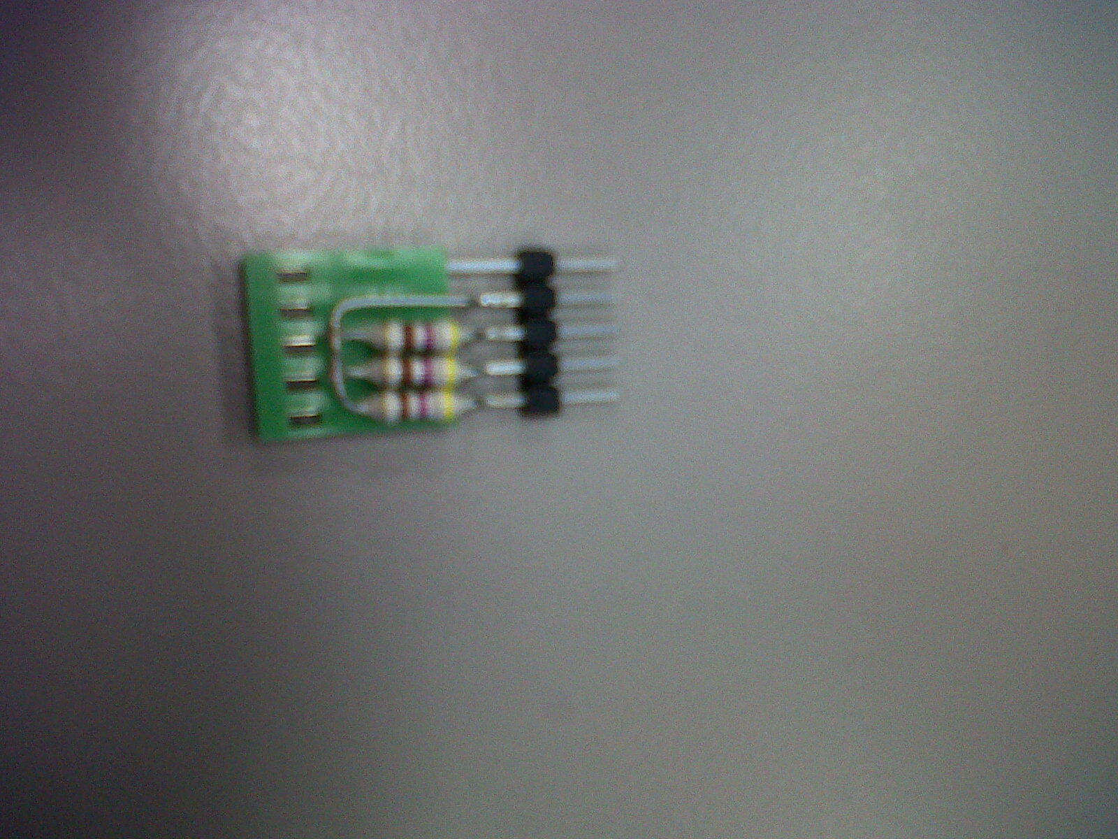
    To quickly test this try and build a connector as you can see attached, I have with success used the connector to get the QEP signals.

    Could you try and build such a pullup circuit and see if this helps with your signals from the encoder, and give some feedback on the result.

    Kind Regards,

    Kristen

  • Hello Kristen,

    the Encoder is able to deliver up to 70mA. The levels are 0.23V for Low and 5.1V for High - it should be ok. gMotorVars.EstState changes the value from EST_State_Idle, EST_State_Rs to EST_State_Online - but I could not feel any vibrations.


    Uwe

  • Hi Uwe, 

    Could you check if the USER_MOTOR_ENCODER_LINES is defined correctly in user.h? 

  • Hi Swaroop,

    I think, it is ok:

    #elif (USER_MOTOR == My_Motor_v3)                       // Name must match the motor #define - Dunkermotoren BG 42X15 24V
    #define USER_MOTOR_TYPE                 MOTOR_Type_Pm       // Motor_Type_Pm (All Synchronous: BLDC, PMSM, SMPM, IPM) or Motor_Type_Induction (Asynchronous ACI)
    #define USER_MOTOR_NUM_POLE_PAIRS       (4)                 // PAIRS, not total poles. Used to calculate user RPM from rotor Hz only
    #define USER_MOTOR_Rr                   (NULL)              // Induction motors only, else NULL
    #define USER_MOTOR_Rs                   (0.535)         // Identified phase to neutral in a Y equivalent circuit (Ohms, float)
    #define USER_MOTOR_Ls_d                 (0.000375)      // For PM, Identified average stator inductance  (Henry, float)
    #define USER_MOTOR_Ls_q                 (0.000375)      // For PM, Identified average stator inductance  (Henry, float)
    #define USER_MOTOR_RATED_FLUX           (0.0489)        // Identified TOTAL flux linkage between the rotor and the stator (Webers = Volts* Seconds)
    #define USER_MOTOR_MAGNETIZING_CURRENT  (NULL)              // Induction motors only, else NULL
    #define USER_MOTOR_RES_EST_CURRENT      (2.0)               // During Motor ID, maximum current (Amperes, float) used for Rs estimation, 10-20% rated current
    #define USER_MOTOR_IND_EST_CURRENT      (-2.0)              // During Motor ID, maximum current (negative Amperes, float) used for Ls estimation, use just enough to enable rotation
    #define USER_MOTOR_MAX_CURRENT          (2.24)               // CRITICAL: Used during ID and run-time, sets a limit on the maximum current command output of the provided Speed PI Controller to the Iq controller
    #define USER_MOTOR_FLUX_EST_FREQ_Hz     (50.0)              // During Motor ID, maximum commanded speed (Hz, float), ~10% rated
    #define USER_MOTOR_ENCODER_LINES        (500.0)         // Number of lines on the quadrature encoder

    The Encoder is a "RE30-3-500+TI 5V" with 500 lines

    http://www.dunkermotoren.de/data/technical_data/servocomponents/pdf/Inkrementalgeber_RE.pdf#page=1

    I wonder, that I could not feel any vibrations or that there is no swing. I found a Expression for QEP-Speed: gMotorVars.SpeddQEP_krpm but not for QEP-Position.

    I noticed, that the expression "gMotorVars.Speed_krpm" changes the value from -6 to +2 (Q24) in a random way.


    Uwe

  • Thanks Uwe. Let's check off some things:

    First if you are running DRV8312 board, then ensure that the three toggle switches RSTA, RSTB, and RSTC are in the middle position ("MCU"). If using 8301 board, ignore this.

    Ensure that you are building the Lab 12 project meant for the board you are currently using. 

    Ensure that the Position Convert Component is enabled and receiving QEP signal properly. To do this, build and download Lab 12 into the microcontroller, make sure you enable Silicon Real-time mode, and then run the program. Set Flag_enableSys to enable the system. After this, load the SpinTAC object "st_obj" into your expressions window, and collapse it till you see st_obj > vel > conv. This conv object is the Position Convert component which gives you outputs "Vel" (calculated Speed), and "Pos_mrev" (position in Mech revolutions). 

    At this point, spin the motor shaft with your hand in counter clockwise direction (while facing the shaft). If all connections are made right, then Pos_mrev should increase, and Vel should register a positive speed. 

    To see QEP Electrical angle, call DRV_getQepElecAngle() and store the return value in an IQ24 variable.

  • Uwe,

    In looking at the encoder datasheet that you provided it lists the Pulses Per Revolution (PPR) of the encoder.  Typically this number reflects the post-quadrature count of the encoder.  For InstaSPIN-MOTION proj_lab12 we need to set USER_MOTOR_ENCODER_LINES to Counts Per Revolution (CPR).  Typically CPR is represented as (PPR / 4). 

    In order to run the motor the USER_MOTOR_ENCODER_LINES sets up how the eQEP module converts the quadrature signals into the electrical angle of the motor.  If this number is wrong it means that the generated electrical angle is incorrect and the motor will not spin. 

    I would recommend you set USER_MOTOR_ENCODER_LINES to be 125.0 instead of 500.0.  This should be the correct setting for your encoder.

    The way to test this is the following procedure:

    1. Build & download proj_lab12

    2. Enable Silicon Real-time Mode

    3. Run the program

    4. Set gMotorVars.Flag_enableSys to 1

    5. Add this expression into the expressions window "st_obj.vel.conv.Pos_mrev", this is a Q24 value

    6. Manually rotate the motor approximatly 1 revolution in the anti-clockwise direction

    7. As you rotate the motor you should see the value in "st_obj.vel.conv.Pos_mrev" be near 1.0, this will indicate that your encoder is configured correctly.

    Good Luck!

  • shame on me: I used a wrong order at J4 - index and track-A was interchanged.

    The hint with st_obj.vel.conv.Pos_mrev has shown, that the value for position got wrong - a check with the oscilloscope has shown beautiful signals, but they was at the wrong pins :-(

    The line number was correct - it is 500 - the resolution is 2000. But it is not well-defined in the datasheet.

    Thank you very much for your support!!


    Uwe

  • I am attempting to run lab12 using the DRV8312EMV and to no avail. When setting enableSys and Run_Idenify to '1', my motor partially spins and then locks up.

    I've checked my wiring and am certain it is correct. I powered the motor's hall sensors with an external power supply as suggested in an earlier post. I am using the Telco motor and connecting the sensors to J4 on the board (I even tried J10 and that didn't work as well).

    Any help would be greatly appreciated. :-)

    ~Cristhian

  • Cristhian,

    Lab12 works with a QEP style encoder in order to generate the electrical angle.  We do not currently have a project that uses the Halls in order to do FOC.  Does your Telco motor have an attached encoder?

  • No it doesn't. The motor that came with the kit didn't have any information regarding what the wire leads of the motor were. In another post, a TI employee forwarded the specs for the motor that came with my kit. According to that data, it is saying I have 3 hall senor.


    If lab12 doesn't work with hall sensors than how can I interface them with the DRB8312 board? J10 is dedicated to Hall sensors.

    ~Cristhian

    http://e2e.ti.com/support/applications/motor_drivers/f/38/p/273144/1185136.aspx#1185136

  • Cristhian,

    The DRV8312 board uses J4 as the encoder interface.  It is dedicated to work with QEP type encoders.  There are other motors from TI that have a built-in encoder (LVSERVOMTR, HVPMSMMTR, HVACIMTR).  In those labs we don't use J10, if you want to write code that makes use of the Hall sensors you are free to do so.