This thread has been locked.

If you have a related question, please click the "Ask a related question" button in the top right corner. The newly created question will be automatically linked to this question.

can PFC Circuit place in the secondary circuit of switch power supply?

Other Parts Discussed in Thread: AMC1200

dear :

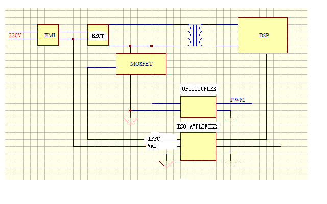
now i want to design A digital power supply; in my app ,i use one DSP to control PFC circuit  and switch power  circuit , the power for dsp is come from the  auxiliary power supply is +3.3v and GND ; but the  reference ground  for Signal about the pfc (current  and volt) is 0V ;so those two reference ground GND and 0v are not the same ,i want to use  Optocoupler. is it right ?can it Realization?

  • Hello,

    Yes, it could look something like your picture.  The problems you'll run into are (1) powering the DSP at startup, (2) getting VAC across the isolation boundary cheaply, and (3) powering the primary side of the ISO Amp.

    Unless there is more going on in your circuit (specifically on the secondary side of the flyback), I might recommend putting your DSP on the primary side.  If the DSP is on the primary side, the only signal that will need isolation is probably the output voltage.  You'd then use some switching supply to generate the DSP's 3.3V supply from the AC-line.

    What are you looking at for the iso amp?  Something like the AMC1200?


    Thank you,
    Brett

  • hello Brett:

    i want to design about 3000kw pfc kit with 390VDC output by use dsp28035 .can i take the example about 750w pfc kit to design it ? thanks

  • Hello,

    You'll need to edit the software some in order to make it match your power topology/pinout/etc.  You'll also need to retune the control loops. 

    However, it should serve as a good starting point.


    Thank you,
    Brett