This thread has been locked.

If you have a related question, please click the "Ask a related question" button in the top right corner. The newly created question will be automatically linked to this question.

How can I achieve a good duty accuracy using a low frequency PWM carrier?

Hi everyone,

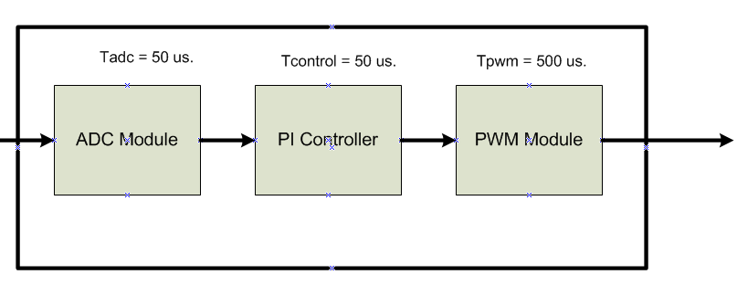
In my project, analog inputs must be sampled at Ts=50 us. These signals are used as modulating waves to generate PWM signals. However, the PWM period must be lower than Ts (for example Tpwm = 500us)  because the hardware connected to the pwm signals has limitations on switching frequency. It means that ADC module adquires several samples per PWM period. If I only use the first ADC sample to compare, the duty cycle of the PWM signal will have poor accuracy because the modulating signal can change significantly during the PWM period. In the other hand, if I want to use more than one sample I should use the immediate load mode (to my best knowledge),which seems to be pretty tricky. Then, the question is:

How can I achieve a good duty accuracy using a low frequency PWM carrier?

Thanks, Juan

  • Hi Juan,

    I think you want to use 2 ePWMs, one at the sampling frequency of the ADC (say 20KHz) and the other at the ePWM control frequency (say 2KHz).  Keep these ePWMs synchronized, and don't enable the ADC sampling ePWM to the pin.

    Do you think this will work?

  • Hi Devin,

    I afraid I don't understand how your solution works. Could you explain it in more detail? I can't see how to use these two PWMs to achieve my goal.

    Here is a brief explanation of my framework in order to give your a better insight into my problem.

    My system is composed by three block: ADC Module, PI Controller and PWM Module. The status of the three modules should be updated at T=50us (including the PWM module) but the PWM period must be lower. The figure below represents my system.

  • You would setup ePWM1 with a period of 50us (20KHz) and you would setup ePWM1 to trigger the ADC each period.  On the last ADC SOC triggered by ePWM1, you would trigger an ISR and run your control algorithms based on the ADC results.  ePWM1 does not come out to a pin; it is used strictly to trigger the ADC periodically.

    ePWM2 is set to a period of 500us (2KHz).  When ePWM2 is started initially, ePWM1 is also started at the same time, such that every 10 ePWM1 periods equals 1 ePWM2.  In the control algorithm, which runs every 50us based on ePWM1 period, you can write your computed changes to ePWM2.  ePWM2 is brought out to a pin and used to control the external system of interest.

  • Thanks Devin,

    Now, It is clear for me. I think I could work for me.

    I will keep you up to date.

    Thanks, Juan.