


Hello TI Team,
we are implementing 3 phase 10kW PFC with code that you mentioned before as a post
http://e2e.ti.com/support/microcontrollers/c2000/f/171/t/262867.aspx
also Mr. Yunus Karaborek (TI Turkey team member) supported us the same code and hardware schematics. we are running the code with tmdsdock28035 experimenter kit and we have nearly the same hardware structure for reading current and voltage samples. only changes are, we are using ACS709LLFTR-20BB-T (56mV/1Amp) current sense IC instead your custom design current transformer and also we are using TI opa348 instead TI opa350 for voltage sensing. All sensing offset voltages have been set to 1.65V as recommended (dc link offset is 0V). switching frequency and dead time have been set to 40 kHz and 2us respectively.
Our main problem occurs while input line currents are low. so that our low side PWM outputs have spaces periodically while line voltage goes to positive. also this makes 50hz audible noise on pfc inductors. you can see the oscilloscope view below. when we get higher line currents, empty pwm spaces disappears and it works fine.
voltage and current graphs are inverted.
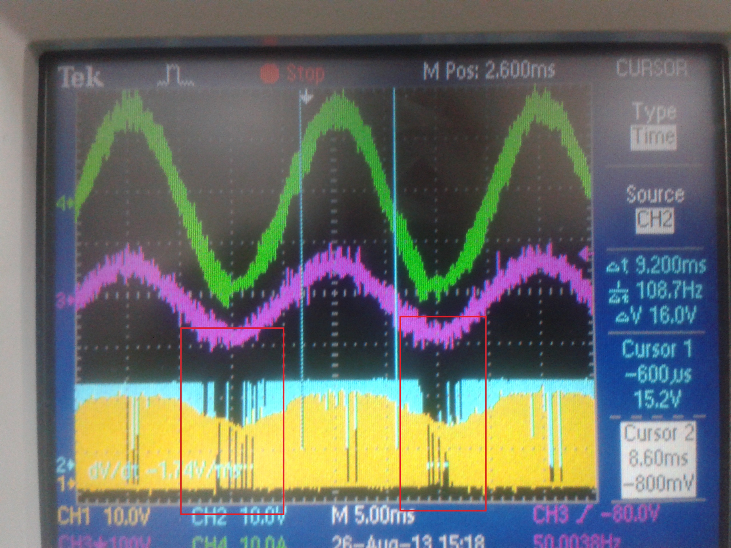
yellow channel, high side gate signals with bootstrap. (we fixed it with isolated supply. now it works fine)
blue channel, low side gate signals. has spaces
pink one is R phase line voltage (inverted)
green one is R phase inductor current (inverted)
how can we fix pwm spaces on low side ?
also we can send you more information (technical data, project details etc) details via e-mail communication.
thanks for your kind help
Alper Goynusen
Hardware Designer / Msc.EE.


