This thread has been locked.

If you have a related question, please click the "Ask a related question" button in the top right corner. The newly created question will be automatically linked to this question.

CPU Timer 0 Won't Set Interrupt Flag When Count Reaches Zero on TMS320F28069

Other Parts Discussed in Thread: TMS320F28069, CONTROLSUITE

Can't get interrupt with CPU Timer 0 working with TMS320F28069.

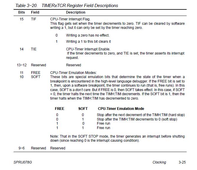
CpuTimer0Regs.TCR.bit.TIF sets to 1, and the interrupt is enabled with PieCtrlRegs.PIEIER1.all = 64, but won't vector to the ISR and PieCtrlRegs.PIEIFR1.all = 0, seeming to indicate that the interrupt flag didn't set.

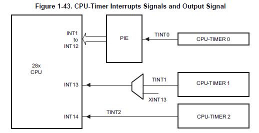
This should be interrupt TINT0 at int1.7 in the PIE, hence the 64 (1000000b) for PieCtrlRegs.PIEIER1.all above.

I've successfully set up and used the 3 XINTs for a high-speed motor drive, but now need an interrupt from the timer to activate when timer count done at CpuTimer0Regs.TCR.bit.TIF = 1.

What's wrong here?

Thanks.

  • Hello!

    You can try to use this example project to resolve your issue ti\controlSUITE\device_support\f2806x\v136\F2806x_examples_ccsv5\cpu_timer\

    Regards,

    Igor 

  • Thanks Igor, that helped me find the problem.

    The Example file has a line,

    CpuTimer0Regs.TCR.all = 0x4001; // Use write-only instruction to set TSS bit = 0

    That 4 in this hex number writes 1 to the TIE bit in the TIMER0TCR register.

    When I put CpuTimer0Regs.TCR.bit.TIE in the watch window, the bit was 0, hence the Timer 0 interrupt was disabled.

    So I just added this line,

    CpuTimer0Regs.TCR.bit.TIE = 1 ;

    and the interrupt now works.

    My mistake was that I thought this code would set the TIE:

    PieCtrlRegs.PIEIER1.bit.INTx7 = 1 ;

    But it doesn't.

    My remaining question is what does PieCtrlRegs.PIEIER1.bit.INTx7 = 1 do?

    It seems redundant with setting the TIE, but it does not set it.

    Again, thank you.

    (p.s. Any relation to theee Gorbachev?)

  • Hello 78Sys!

    78Sys said:

    My remaining question is what does PieCtrlRegs.PIEIER1.bit.INTx7 = 1 do?

    It seems redundant with setting the TIE, but it does not set it.

    There is comment  "Enable TINT0 in the PIE: Group 1 interrupt 7" before this line in cpu_timer example. There is not relation with TIE. I think this figure explains the purpose of this line:

    Thus Timer0 interrupt works through PIE module where one from CPU interrupts is appointed to one through setting PIEIER.

    78Sys said:

    (p.s. Any relation to theee Gorbachev?)

    No, unfortunately (or fortunately) we are from different family trees :-)

    Good luck,

    Regards,

    Igor


  • Thanks Igor,

    problem solved, working well.

  • Hi 78Sys!

    I'm happy to learn about it!

    Good luck,

    Igor

  • A related question, relating to the same timer in an older version DSP (F2812).  Looking over some old code, I notice that both in my own code, and in the example code from TIDCS software, the interrupt routine for the CPU timer does not appear to reset the interrupt flag.  And yet, it works fine...gives me a new interrupt each time the counter reaches 0.

    That is, I would think that I would need a line of code like this:

     CpuTimer0Regs.TCR.bit.TIF = 1;

    to clear the interrupt flag, and that without this line, I should get a new interrupt immediately on return.  But I do not get a new interrupt until the counter reaches 0.  How does this work exactly.  Does TIF get reset automatically at some point? Or does the timer generate a pulse that gets latched by the PIE?

    Thanks

  • Hi Michael!

    Maybe this will clear your question

    Regards,

    Igor

  • Michael,

    The PIE is edge-triggered, so there should never be a second interrupt due to a signal staying active.

    I think the TIF bit is just there if you want an easy way to poll for a timer overflow. It doesn't reflect the true state of the TINT0n signal.

  • Hi Adam, Igor

    In the SPRU078F (System Control and Interrupts), there is a general statement about interrupts coming to the PIE:

    An interrupt-generating event occurs in a peripheral. The interrupt flag (IF) bit
    corresponding to that event is set in a register for that particular peripheral.
    If the corresponding interrupt enable (IE) bit is set, the peripheral generates
    an interrupt request to the PIE controller. If the interrupt is not enabled at the
    peripheral level, then the IF remains set until cleared by software. If the
    interrupt is enabled at a later time, and the interrupt flag is still set, the interrupt
    request is asserted to the PIE.
    Interrupt flags within the peripheral registers must be manually cleared. See
    the peripheral reference guide for a specific peripheral for more information.

    From this, I would have thought that the TIF flag would need to be cleared by the instruction

       CpuTimer0Regs.TCR.bit.TIF=1;

    However, it appears that Adam is correct...without this instruction, the TIF bit stays set continually, but apparently there is another bit which is hidden from the software which actually causes the interrupt and toggles automatically at some point, so that the PIE will see an edge each time the CPUTimer0 counts down to 0.

    Curious...we used some TI example code as a basis for the interrupt service routine for CPUTimer0, without really reading all the documentation carefully.  It has worked fine for years, and now when I re-read the documentation to make some changes, I discover that it works differently than I would have thought.

    Wonder what would happen if the counter reached 0 when the TIE bit was at 0, and then when the counter was no longer at 0, I were to set the TIE bit to 1.  Would I get an interrupt immediately, or only when the counter reaches 0 again?

    It would be nice if this were documented clearly. 

  • Hi, Michael!

    Michael Greenspan said:

    Would I get an interrupt immediately, or only when the counter reaches 0 again?

    In my opinion "when the counter reaches 0 again". Otherwise, the TINT0 interrupt mechanism is something dark generally. At least for me.

    Regards,

    Igor

  • Michael,

    I agree that the documentation is unclear. I'll see about updating it when I get a chance.

  • Hi ... I was reading this post because I was curious myself about this issue. Based on the paragraph that you post, when the counter reaches 0, that EVENT will set the TIF (if not arlready set) and will try to set the corresponding Flag in the PIE. Because the IE in the peripheral is disabled, the later will not happen. Later on if the IE of the peripheral is enabled, the peripheral remembers that there has been an interrupt (e.g. TIF set) and it will set the PIE flag. What i don't know is what happens if I disable and enable TIE again without clearing the TIF. Chances are that another interrupt will be generated. I really don't know.
  • Carlos,

    It's probably better to temporarily disable interrupts using the PIE instead of the peripheral modules. I don't know if all of the peripherals have consistent behavior.

    As was mentioned earlier in the thread, the TIF flag doesn't reflect the actual state of the interrupt signal. I don't think clearing and setting TIE would generate another interrupt, but I'd have to test it to be sure.