


Other Parts Discussed in Thread: DAC8571
Hi!!
I have some problems with the I2C communication between F28069 Piccolo controlSTICK and TI-DAC8571.
I check the analog output signal of DAC with oscilloscope and I use the "Expressions" command on Code Composer in order to change the value trasmitted to the DAC. The output values are correct in general, but there are some gap in the range (0-3.3V) in which the output signal is wrong (see picture,Analog DAC output signal 3, signal 2 SCL, signal 1 SDA):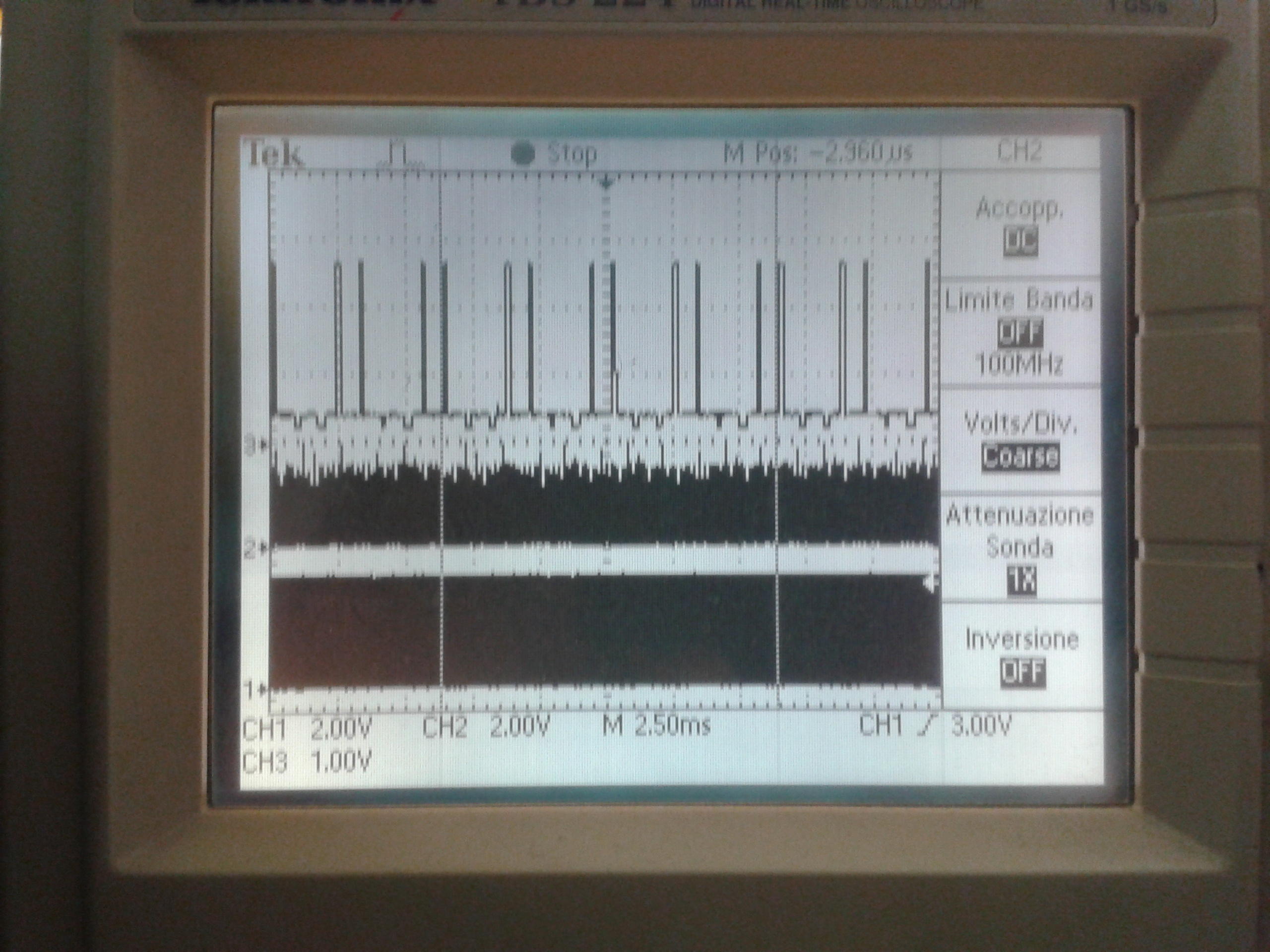


In addition, after a while CCS shows this error message:

This is my code:
//###########################################################################
//
// FILE: Example_2806xI2c_eeprom.c
//
// TITLE: F2806x I2C 2Byte-1Dato
//
//
//
// Description:
//
//Send to DAC8571 data by I2C module
//
//
//###########################################################################
// $TI Release: 2806x C/C++ Header Files V1.10 $
// $Release Date: April 7, 2011 $
//###########################################################################
#include "DSP28x_Project.h" // Device Headerfile and Examples Include File
// Note: I2C Macros used in this example can be found in the
// F2806x_I2C_defines.h file
// Prototype statements for functions found within this file.
void I2CA_Init(void);
Uint16 I2CA_WriteData(struct I2CMSG *msg);
interrupt void i2c_int1a_isr(void);
void pass(void);
void fail(void);
int32 e=0;
#define I2C_SLAVE_ADDR 0x004C // Per modificare l'address dello slave
#define I2C_NUMBYTES 3
int *data;
int data2= 0xCC;
int data4= 0xCC;
int controlbyte=0x10;
int a=0, b=0;
// Global variables
// Two bytes will be used for the outgoing address,
// thus only setup 14 bytes maximum
void main(void)
{
Uint16 Error;
Uint16 i;
// Step 1. Initialize System Control:
// PLL, WatchDog, enable Peripheral Clocks
// This example function is found in the F2806x_SysCtrl.c file.
InitSysCtrl();
// Step 2. Initalize GPIO:
// This example function is found in the F2806x_Gpio.c file and
// illustrates how to set the GPIO to it's default state.
// InitGpio();
// Setup only the GP I/O only for I2C functionality
InitI2CGpio();
// Step 3. Clear all interrupts and initialize PIE vector table:
// Disable CPU interrupts
DINT;
// Initialize PIE control registers to their default state.
// The default state is all PIE interrupts disabled and flags
// are cleared.
// This function is found in the F2806x_PieCtrl.c file.
InitPieCtrl();
// Disable CPU interrupts and clear all CPU interrupt flags:
IER = 0x0000;
IFR = 0x0000;
// Initialize the PIE vector table with pointers to the shell Interrupt
// Service Routines (ISR).
// This will populate the entire table, even if the interrupt
// is not used in this example. This is useful for debug purposes.
// The shell ISR routines are found in F2806x_DefaultIsr.c.
// This function is found in F2806x_PieVect.c.
InitPieVectTable();
// Interrupts that are used in this example are re-mapped to
// ISR functions found within this file.
// EALLOW; // This is needed to write to EALLOW protected registers
//PieVectTable.I2CINT1A = &i2c_int1a_isr;
//EDIS; // This is needed to disable write to EALLOW protected registers
// Step 4. Initialize all the Device Peripherals:
// This function is found in F2806x_InitPeripherals.c
// InitPeripherals(); // Not required for this example
I2CA_Init();
// Enable interrupts required for this example
// Enable I2C interrupt 1 in the PIE: Group 8 interrupt 1
PieCtrlRegs.PIEIER8.bit.INTx1 = 1;
// Enable CPU INT8 which is connected to PIE group 8
IER |= M_INT8;
EINT;
//Impostazioni I2C
I2caRegs.I2CSAR = I2C_SLAVE_ADDR; //Set slave address
I2caRegs.I2CCNT = I2C_NUMBYTES; //Number of bytes to transfer
//I2caRegs.I2CFFTX.all = 0x6000; //enable FIFO mode and reset TX FIFO
//Invia il byte di controllo e i due bytes di dato
for(;;){
I2caRegs.I2CDXR =controlbyte; //Send data[0-3]
I2caRegs.I2CDXR = data4; //Store in next FIFO level
I2caRegs.I2CDXR = data2; //Store in next FIFO level
I2caRegs.I2CMDR.bit.TRX = 1; //Set to Transmit mode
I2caRegs.I2CMDR.bit.MST = 1; //Set to Master mode
I2caRegs.I2CMDR.bit.FREE = 1;//Run in FREE mode
I2caRegs.I2CMDR.bit.STP = 1; // release the bus after Tx
I2caRegs.I2CMDR.bit.STT = 1; //Send the start bit, transmission will follow// while(I2caRegs.I2CSTR.bit.XRDY==0){}; //Do nothing till bus is free
}
// end of write section
} // end of main
void I2CA_Init(void)
{
// Initialize I2C
I2caRegs.I2CSAR = 0x004C; // Slave address - EEPROM control code
I2caRegs.I2CPSC.all = 6; // Prescaler - need 7-12 Mhz on module clk
I2caRegs.I2CCLKL = 10; // NOTE: must be non zero--> setta l'intervallo di tempo in cui il CLock è basso
I2caRegs.I2CCLKH = 5; // NOTE: must be non zero--> setta la durata di tempo in cui il Clock è alto
I2caRegs.I2CIER.all = 0x24; // Enable SCD & ARDY interrupts
I2caRegs.I2CMDR.all = 0x0020; // Take I2C out of reset
// Stop I2C when suspended
I2caRegs.I2CFFTX.all = 0x6000; // Enable FIFO mode and TXFIFO
I2caRegs.I2CFFRX.all = 0x2040; // Enable RXFIFO, clear RXFFINT,
return;
}
//===========================================================================
// No more.
//===========================================================================
Thanks for your disponibility.
Best wishes.
Dario


